<6. Operation>
59
IM 01E24A01-01EN
(4) Taking care not to entangle the cables, tighten the two
screws on the display.
(5) Install the cover.
WARNING
To prevent electric shock and maintain performance,
do not remove the safety cover.
NOTE
The hardware switches are adjacent. Special care
should be taken when making switch settings.
Accordingly, special care should be taken when making
switch settings.
● Setting of Burnout Switch
(Except F
OUNDATION
eldbus communication)
The burnout function sets the direction of current output
in situations where the CPU has become damaged.
Upon shipment from the manufacturing plant, the burnout
direction is set to High (i.e., >21.6 mA); however, in cases
where the optional codes C1 or C2 have been specied,
the output direction will be set to Low (i.e., <2.4 mA).
Modication of the burnout direction must be carried out
using the burnout switch (SW1-1) (See Figure 6.3.1).
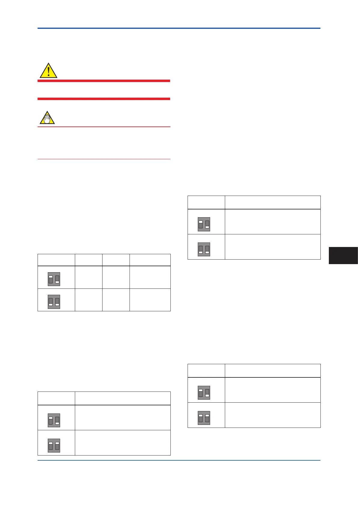
Table 6.3.1 Burnout switch (SW1-1)
Position of
Switch
Burnout
Direction
Burnout
Output
Description
1 2
ON
OFF
H
L
High > 21.6 mA
When optional code
C1 or C2 is not
specied, the setting
is “High”.
1 2
ON
OFF
H
L
Low < 2.4 mA
When optional
code C1 or C2 is
specied, the setting
is “Low”.
● Setting of Write Protect Switch
(Except F
OUNDATION
eldbus communication)
The write protect function is to prevent the overwriting of
parameters.
Write protection can be carried out using either the write
protect switch (SW1-2) (See Figure 6.3.1) or software
function with parameter setting. If either of these items is
activated, the overwriting of parameters will be prohibited.
Table 6.3.2 Write protect switch (SW1-2)
Position of
Switch
Write Protect Function
1 2
ON
OFF
H
L
OFF (Factory setting)
Parameter can be overwritten.
1 2
ON
OFF
H
L
ON
Parameter can not be overwritten.
● Setting of Simulation Switch (Only for
F
OUNDATION
eldbus communication)
The simulation function simulates the input of a function
block and lets it operate as if the data was received from
the transducer block. It is possible to conduct testing for
the downstream function blocks or alarm processes.
A SIMULATE_ENABLE switch is mounted in the
transmitter amplier. This is to prevent the accidental
operation of this function. When this is switched on,
simulation is enabled. (See table below) To initiate the
same action from a remote terminal, if REMOTE LOOP
TEST SWITCH is written to the SIM_ENABLE_MSG
parameter (index 2922) of the resource block, the
resulting action is the same as is taken when the above
switch is on. Note that this parameter value is lost when
the power is turned OFF. In simulation enabled status,
an alarm is generated from the resource block, and
other device alarms will be masked; for this reason the
simulation must be disabled immediately after using this
function.
Table 6.3.3 Simulation Switch (SW1-1)
Position of
Switch
Simulation Function
1 2
ON
OFF
H
L
ON:
Simulation function enabled.
1 2
ON
OFF
H
L
OFF:
Simulation function disabled.
● Setting of Write Lock Function Switch (Only
for F
OUNDATION
eldbus communication)
The transmitter is provided with a write lock function to
restrict write operations to blocks and prevent inadvertent
writing of parameter data. To enable this function, use
the write lock switch (Hard W Lock) or the WRITE_
LOCK (index 1034) (Soft W Lock). To enable write lock
function, set parameter in Feature Selection of Resource
Block. Read IM 01E21A02-03EN ADMAG TI Series
AXG, AXW Magnetic Flowmeter F
OUNDATION Fieldbus
Communication Type 5.12.
Table 6.3.4 Write Lock Switch (SW1-2)
Position of
Switch
Write Lock Function
1 2
ON
OFF
H
L
OFF:
Write Lock function disabled.
(It depends on the setting in Feature Selection.)
1 2
ON
OFF
H
L
ON:
Write Lock function enabled.
(It depends on the setting in Feature Selection.)
Operation
6
 Loading...

