<6. Operation>
62
IM 01E24A01-01EN
6.3.3 AXFA11 Remote Transmitter
IMPORTANT
•
Removing and installing the cover are necessary for
hardware switches. Perform removing and installing the
cover as described in Subsection 4.4.5. When opening
the cover, wait for more than 20 minutes after turning off
the power. This work must be carried out by the trained
personnel having knowledge of safety standard.
•
To preserve the safety, do not touch the electrical circuit
and the cables except the setting switches.
(1) Loosen the two display unit mounting screws while
supporting it with your hand (See Figure 6.3.5).
F0614.ai
Display unit mounting
screws (x2)
Figure 6.3.5 Removing Mounting Screws of Display Unit
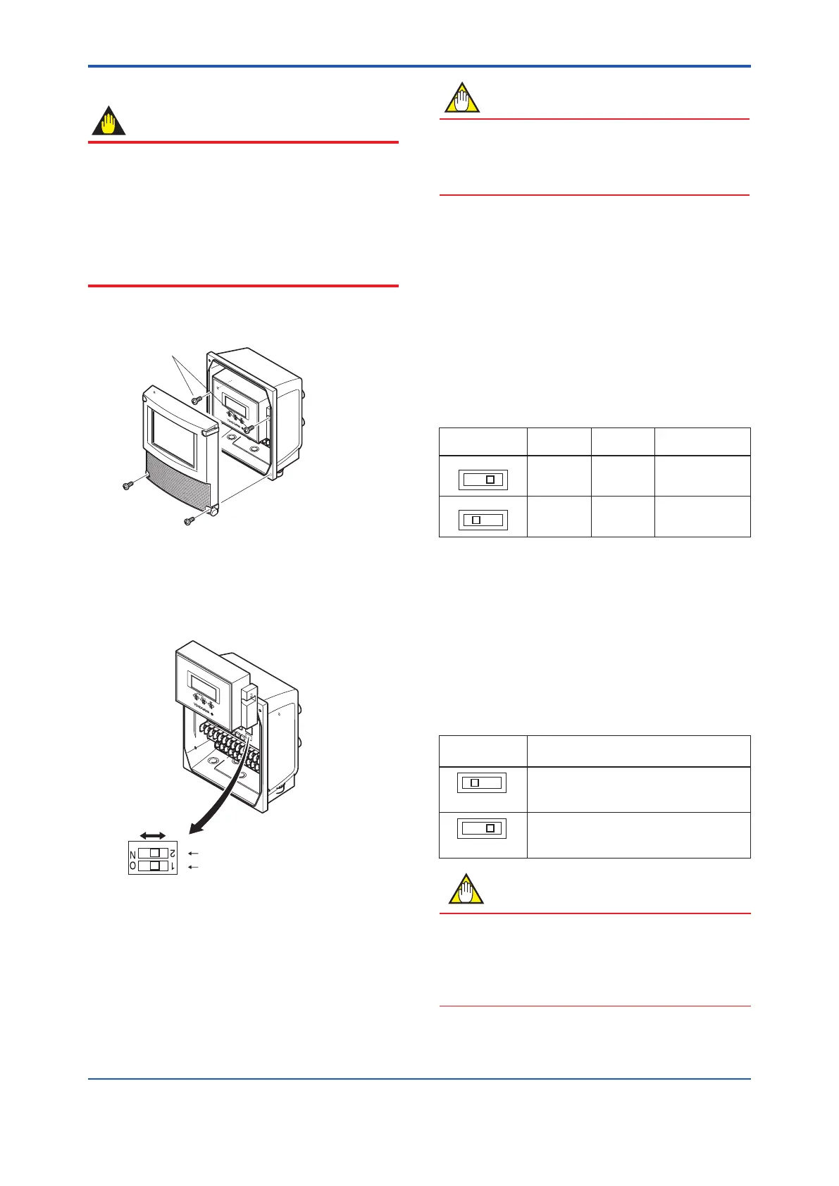
(2) Taking care of the connector and cable connecting
to the display unit, move the display unit as shown
in Figure 6.3.6, and set the switches. Never remove
connector in this case.
Enable Protect
Switch 1 2 Burnout switch
Switch 2 1 Write protect switch
Low High
Figure 6.3.6 Hardware switches
(3) After setting the switches, taking care not to entangle
the cables, install the display unit with two mounting
screws.
(4) Install the cover.
NOTE
On the front of the amplier, the burnout switch (i.e.,
Switch 1) and the write protect switch (i.e., Switch 2) are
located adjacent to each other. Accordingly, special care
should be taken when making switch settings.
(1) Setting of Burnout Switch
The burnout function sets the direction of current output in
situations where the CPU has become damaged.
Upon shipment from the manufacturing plant, the burnout
direction is set to High (i.e., 25 mA); however, in cases
where the optional codes C1 have been specied, the
output direction will be set to Low (i.e., 0 mA).
Modication of the burnout direction must be carried
out using the burnout switch (i.e., Switch 1) (See Figure
6.3.6).
Table 6.3.10 Burnout switch (Switch 1)
Position of
Switch
Burnout
Direction
Burnout
Output
Description
High 25 mA
When optional code
C1 is not specied,
the setting is “High”.
Low 0 mA
When optional code
C1 is specied, the
setting is “Low”.
(2) Setting of Write Protect Switch
The write protect function is to prevent the overwriting of
parameters.
Write protection can be carried out using either the write
protect switch (Switch 2) (See Figure 6.3.6) or software
function with parameter setting.
If either of these items is activated, the overwriting of
parameters will be prohibited.
Table 6.3.11 Write protect setting switch (Switch 2)
Position of
Switch
Write Protect Function
Enable (Factory setting)
Parameter can be overwritten.
Protect
Parameter can not be overwritten.
NOTE
• If the hardware switch is set to “Protect”, the condition
of preventing parameter overwriting kept until the
switch is set to “Enable”.
• For AXFA11, read the user’s manual of applicable
communication type as listed in Table 1.1.
 Loading...

