IM 01E21A21-02EN
<2. Safety Instrumented Systems Installation>
5
2.2.4 Setup
Set the ranges and units via the BRAIN or HART conguration tool. After conguration, make sure that they
are set correctly. The calibration of this product must be carried out after parameters are set. For its parameter
settings, read Chapter 4 and Chapter 5 in the user’s manual of applicable communication type as listed in
Table 1.1.
2.2.5 Required Parameter Setting
The following parameters as shown in Table 2.2.1 and Table 2.2.2 are required to be set in order to preserve
this product for that safety level.
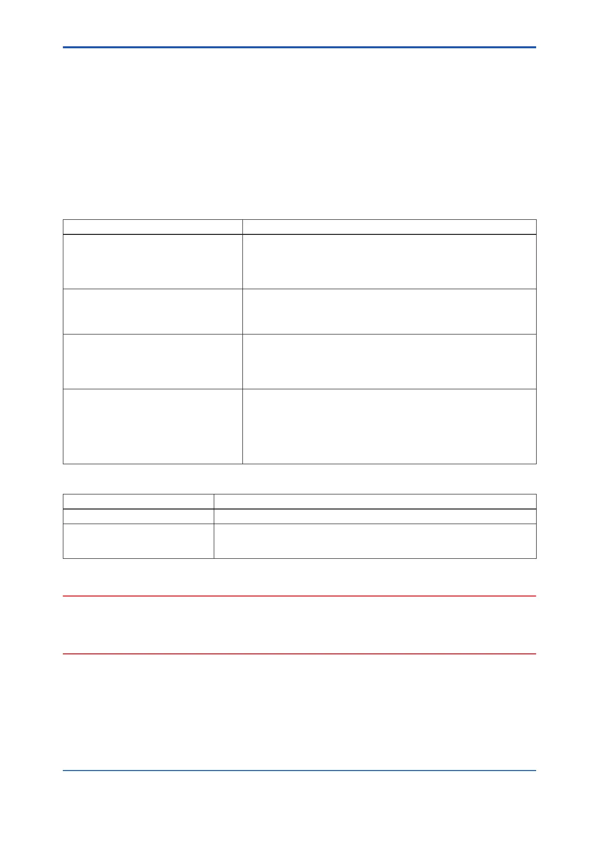
Table 2.2.1 Setup by Parameters
Item Explanation
BRAIN: G04:AO1 ALM OUT
HART Menu Path:
Device root menu
▶Detailed setup▶
Analog output/input▶Analog output 1▶
AO1 alarm out
This function is to output the signal through the “Analog Output 1” when
this product is detected its alarm.
Set the “Analog Output 1” as “> 21.6 mA” or “< 2.4 mA” when this product
is used for SIS.
BRAIN: H50:SET SIL
HART Menu Path:
Device root menu
▶Detailed setup▶
AUX calculation▶Set SIL
Set this parameter as “Yes” when this product is used for SIS. In this
case, its “Analog Output 1” is xed as “> 21.6 mA” or “< 2.4 mA” when its
alarm was detected. It is able to carry out the burnout function via “Analog
Output 1” without fail when this product is detected its alarm.
BRAIN: H30:DENSITY SEL
HART Menu Path:
Device root menu
▶Detailed setup▶
Process variables▶Density▶
Density value select
Set this parameter as “Fixed value” when the “Analog Output 1” is used
for mass ow measurement.
BRAIN: P22:NEW PASSWORD
HART Menu Path:
Device root menu
▶ Detailed setup ▶
Protection
▶ New password
Set a password of 8 characters (no lowercase letters allowed) to enable
the software write protect function. For detailed setting instructions, please
refer to the respective communication type manuals in Table 1.1. In this
case, do not forget the parameters you set.
When used in instrumented safety systems, at least one of the write
protect switch or the software write protect function must be enabled.
Table 2.2.2 Setup by Hardware
Item Explanation
Burnout switch Select “High” or “Low” for the output when an internal failure was detected.
Write protect switch Enable the write protect function by setting its switch “ON”.
When used in instrumented safety systems, at least one of the write protect
switch or the software write protect function must be enabled.
When using this instrument for Safety Instrumented System (SIS) application, The setting change of this
instrument must be done by personnel should be trained in operation of SIS. Therefore, limit the number of
personnel should be trained in the operation of SIS and who can set the New password or enable the write
protect switch to change the setting.
 Loading...

