Making Preparations for Measurements
2.5 Correcting a Probe Phase
Explanation
Necessity of Probe Phase Correction
The phase of each probe is already corrected so as to approximately match the input capacitance of
the oscilloscope that the probe is intended to be used with. However, the input resistance and input
capacitance each of the input channels of each individual oscilloscope vary. This results in a mismatch
in the voltage divider ratio between low and high frequency signals and causes uneven frequency
characteristics.
There is a variable capacitor for adjusting the division ratio (trimmer) for high frequency signals on
the probe. To correct the phase, you must adjust this trimmer so that flat frequency characteristics are
obtained.
Be sure to correct the phase of a probe that you are using for the first time.
Because the input capacitance varies on each channel, probe compensation is always required when
the probe is switched from one channel to another.
Phase Compensation Signal
The following square wave signal is output from the signal output terminal for probe compensation
adjustment.
Frequency: Approx. 1 kHz
Amplitude: Approx. 1 V
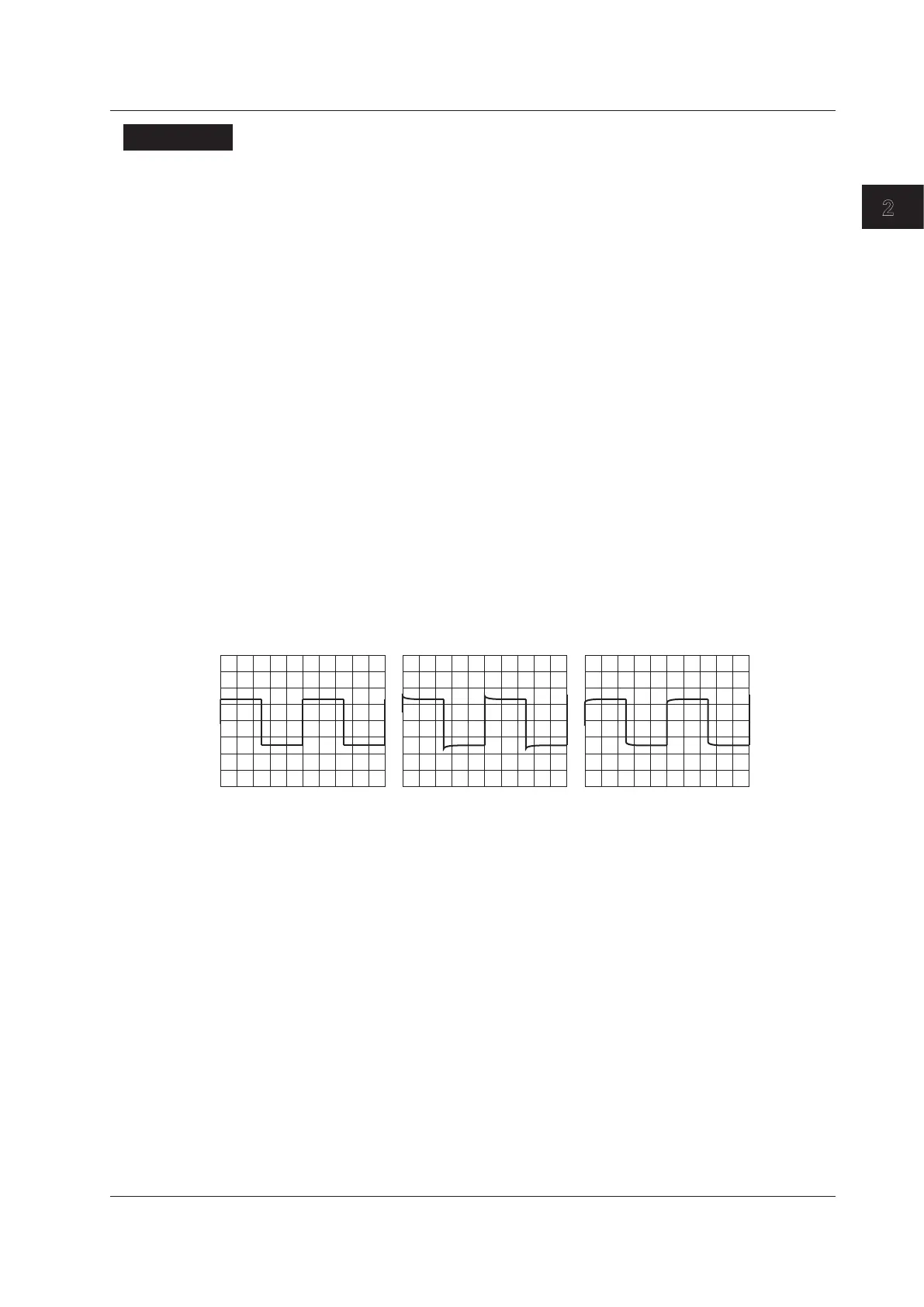
Differences in the Waveform Caused by the Phase Correction of
the Probe
Correct waveform Overcompensated (The
gain in the high frequency
region is too high.)
Undercompensated (The
gain in the high frequency
region is too low.)
2-15
IM DLM4038-03EN
2
 Loading...