10-6
IM 01F06A00-01E
10. EXPLOSION PROTECTED TYPE INSTRUMENT
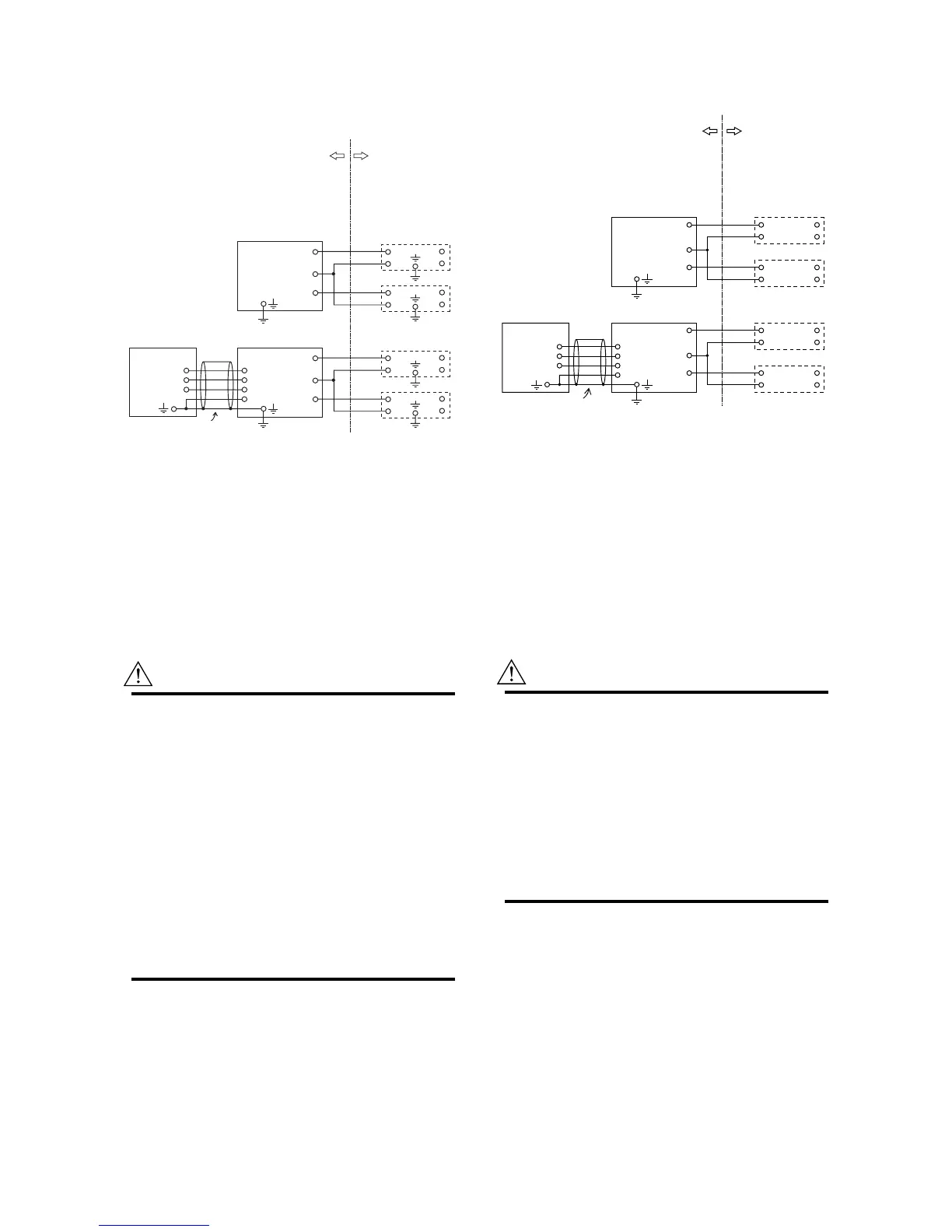
10.2.5 Installation Diagram
Intrinsically Safe (and WARNING)
F100201_1.EPS
[Remote type]
DYA (converter)
SUPPLY
PULSE
A
B
T (*1)
C
A
B
T
DY (flowmeter)
SUPPLY
PULSE
Safety barriers
Safety barriers
[Integral type]
DY-N (flowmeter)
Hazardous Location
Class I, II, III, Division 1,
Groups A, B, C, D, E, F and G,
and Class I, Zone 0, Group IIC
Non Hazardous
Location
DYC: Signal cable
(*1) Wire for T terminal
With temperature sensor type : installed
Without temperature sensor type: not installed
Electrical parameters of vortex flowmeter (DY) and vortex flow
converter (DYA).
Vmax=30V Imax=165mA Pi=0.9W
Ci=12nF Li=0.15mH
Installation requirement between flowmeter, converter and
Safety Barrier
Vt or Voc Vmax It or Isc Imax Po Pi
Ca Ci+Ccable
La Li+Lcable
Vt, Voc, It, Isc, Voc, Ca and La are parameters of barrier.
WARNING
• In any safety barrier used output current must
be limited by a resistor ‘R’ such that Isc=Voc/R.
• Any Single FM Approved Barrier of multiple
barriers FM Approved for this configuration
who’s parameters meet the above installation
requirements.
• Input voltage of the safety barrier must be less
than 250Vrms/Vdc.
• Installation should be in accordance with
National Electrical Code, ANSI /NFPA70.
• Dust-tight conduit seal must be used when
installed in class II and III environments.
• Do not alter drawing without authorization from
FM.
Nonincendive (and WARNING)
Hazardous Location Non Hazardous
Location
Class I, II, Division 2,
Groups A, B, C, D, F and G,
Class III, Division 1, and
Class I, Zone 2, Group IIC
[Integral type]
[Remote type]
DY (flowmeter)
SUPPLY
PULSE
+
+
–
+
–
+
–
+
–
+
–
Power
Supply
Receiver
DY (converter)
DY-N (flowmeter)
SUPPLY
PULSE
+
+
–
+
–
+
–
+
–
+
–
Power
Supply
Receiver
A
B
T
C
A
B
T
(*1)
DYC: Signal cable
(*1) Wire for T terminal
With temperature sensor type : installed
Without temperature sensor type: not installed
Non-incendive field wire parameters of vortex flowmeter (DY)
and vortex flow converter (DYA).
Vmax=30V Imax=165mA Pi=0.9W
Ci=12nF Li=0.15mH
Installation requirement between flowmeter, converter and
general purpose equirement.
Vt or Voc Vmax It or Isc Imax Po Pi
Ca Ci+Ccable La Li+Lcable
Vt, Voc, It, Isc, Po, Ca and La are nonincendive field
wire parameters of general purpose equipment.
F100201_2.EPS
WARNING
• The general purpose equipment must be FM
approved with Nonincendive field wiring param-
eter which meet the above installation require-
ments.
• Installation should be in accordance with
National Electric Code, ANSI/NFPA70.
• Dust-tight conduit seal must be used when
installed in class II and III environments.
• Do not alter drawing without authorization from
FM.
 Loading...


