4-9
IM 01F06A00-01E
4. BASIC OPERATING PROCEDURES
4.5 Operation for the BRAIN
Terminal (BT200)
This section describes the operation procedures using a
BRAIN Terminal (BT200). For details on the functions of the
digitalYEWFLO, refer to 5.3 Parameter List. And also, see
the “Model BT200 BRAIN TERMINAL” Instruction Manual
(IM 1C0A11-01E) for more detailed Information.
4.5.1 Connection Method for the BT200
(1) Connecting the BT200 to a 4 to 20mA DC
Transfer Line
The communication signal of the digitalYEWFLO is
superimposed onto the 4 to 20mA DC analog signal to
be transferred.
digitalYEWFLO
SUPPLY
BT200 BT200 BT200 BT200
Inter mediate
terminals
4 to 20mA DC
Signal
transmission
line
Control room
Receiving
instrument
load
resistance:
250 to 600Ω
Te rminal
Board
SUPPLY
F040501.EPS
Figure 4.4 Communicating for a 4 to 20mA DC Signal
Line
IMPORTANT
The communicable distance of the transmission line is
restricted depending on the wiring method. Refer to 3.
WIRING.
IMPORTANT
After setting a parameter, keep the power on for at
least 30 seconds.
If the power of flowmeter is turned off, a parameter
setting is released.
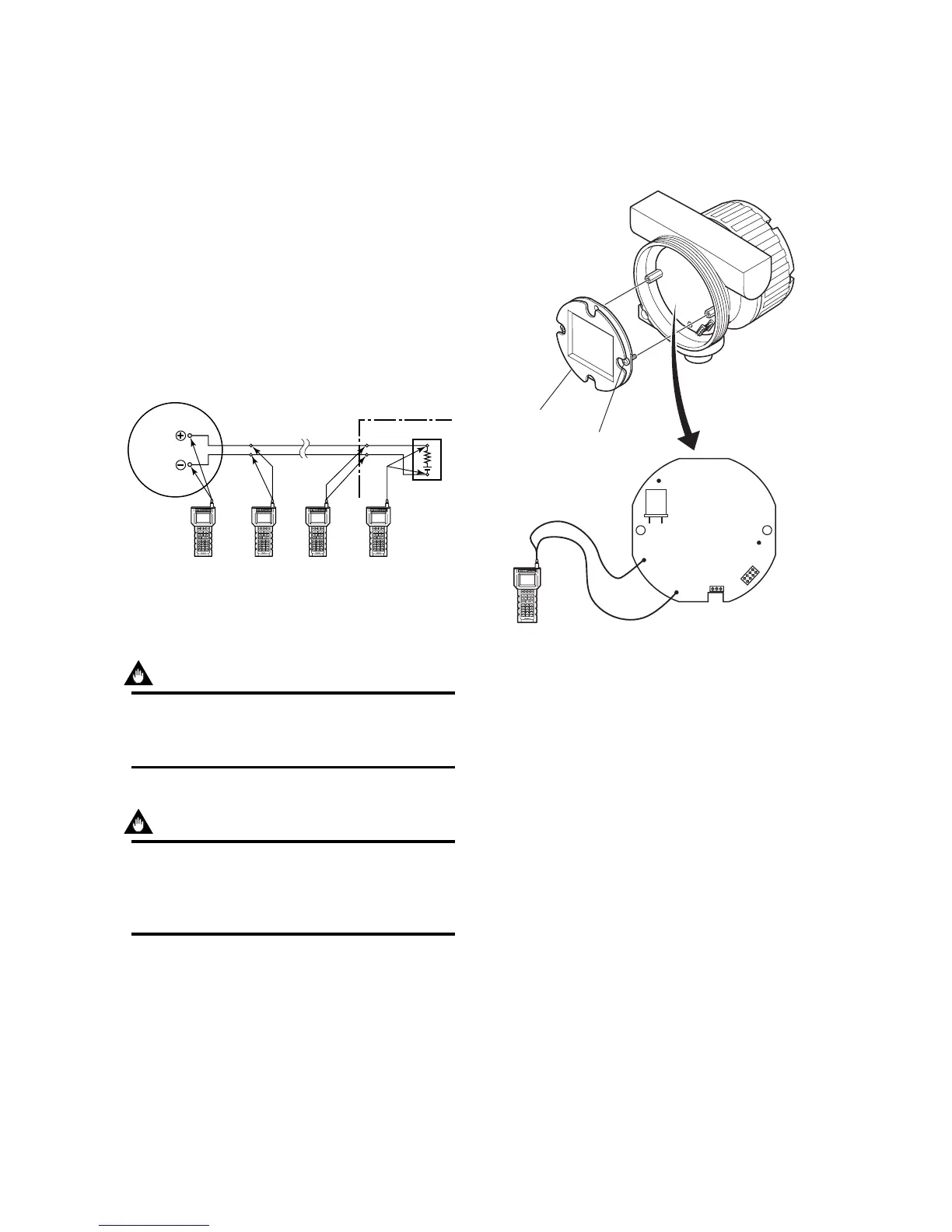
(2) Connecting BT200 to Flow Converter
Removing a cover and indicator, the terminals for brain
communication are provided on the circuit board.
Connect BT200 to the terminal of HHT-COM on the
circuit board.
TP2
COM
HHT
P
F040502.EPS
BT200
Display
Indicator Mounting
Screw (2 PCS)
Circuit board
Figure 4.5 Connection of BT200 to Flow Converter
 Loading...


