3-3
IM 01F06A00-01E
3. WIRING
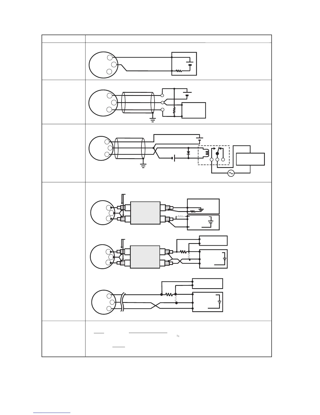
Table 3.1 The connection example for simultaneous analog and pulse and alarm, status output.
+
+
digitalYEWFLO Electrical Terminal
250Ω
24V DC
PULSE
SUPPLY
+
–
Distributor
–
Use the Three-wire shielded cable.
Use the Three-wire shielded cable.
*1 : To avoid the influence of external noise, use an electric counter which fits to the pulse frequency.
*2 : Resistor is not necessary in case of an electric counter which can receive contact pulse signal directly.
Shielded Cable
+
–
+
PULSE
SUPPLY
R
E
digitalYEWFLO Electrical Terminal
Electric counter
*1
*2
Shielded Cable
PULSE
SUPPLY
+
–
+
Mognetic
valve
AC power supply
External Power supply
30V DC, 120mA max
(Contact Rating)
digitalYEWFLO Electrical Terminal
E
Relay
This supply voltage requires a power
sourse with a maximum output
current of no less than E/R.
Analog Output
Pulse Output
Status Output
Alarm Output
Simultaneous
Analog
-Pulse Output
Description
Connection
T030301.EPS
0.1
C (
µF ) × f ( kHz )
⬉ R (k
Ω
) ⬉
120
E (V)
The load resistance should be selected by calculation as shown below.
Example of CEV cable capacitance
6
0.1µF/km
Where
E = Supply voltage (V)
f = Frequency of pulse output (kHz)
R = Value of load resistance (k
Ω
)
C = Cable capacitance (µF)
P = Power ratio of the load resistance
(mW)
P (mW) =
R (k
Ω
)
E
2
(V)
Example 3
In this case, No communi
-cation is possible (when
shielded cable is not used).
The range of load
resistance R for
the pulse output.
Example 1
In this case, Communica
-tion is possible(up to a
distance of 2km when a
CEV cable is used).
Example 2
In this case, Communica
-tion is possible (up to a
distance of 200m when a
CEV cable is used) and R
= 1k
Ω
).
In this case,
Communication is
possible (up to a distance
of 2km when a CEV cable
is used.)
In this case,
No communication is
possible.
In this case,
No communication is
possible.
250
Ω
+
–
+
PULSE
SUPPLY
digitalYEWFLO Electrical Terminal
Recorder or
other instrument
This supply voltage requires
a power sourse with a
maximum output current of
no less than E/R+25mA.
Electric counter
E(16.4 to 30V DC)
Counting input
Common
*1
(or communication medium)
When analog and pulse output are used, the length of communication line is subjected to wiring conditions. Refer to
example 1 to 3. If the communication carries out from amplifier, no need to consider wiring conditions.
+
–
+
For the shielded cables in this
example of flowmeter installation,
use two-wire separately shielded
cables.
This supply voltage requires a
power sourse with a maximum
output current of no less than
E/R+25mA.
The supply voltage requires output
impedance no more than 1/1000 of
R (load resistance).
PULSE
SUPPLY
Shielded Cable
Shield
digitalYEWFLO Electrical Terminal
Outer Jacket
*1
(or communication medium)
250
Ω
(R)
*2
Counting input
Common
Recorder or
other instrument
Electric counter
E(16.4 to 30V DC)
(R)
*2
Electric counter *1
(or communication medium)
+
–
+
250Ω
(R)
*2
E(10.5 to 30V DC)
Counting input
Common
24V DC
PULSE
SUPPLY
Distributor (or communication medium)
Shielded Cable
Shield
digitalYEWFLO Electrical Terminal
For the shielded cables in this
example of flowmeter installation,
use two-wire separately
shielded cables.
This supply voltage requires a
power sourse with a maximum
output current of no less than
E/R.
Outer Jacket
 Loading...


