<Toc> <Ind>
3-5
TI 05C01E02-01E 1st Edition : Oct. 31, 2001-00
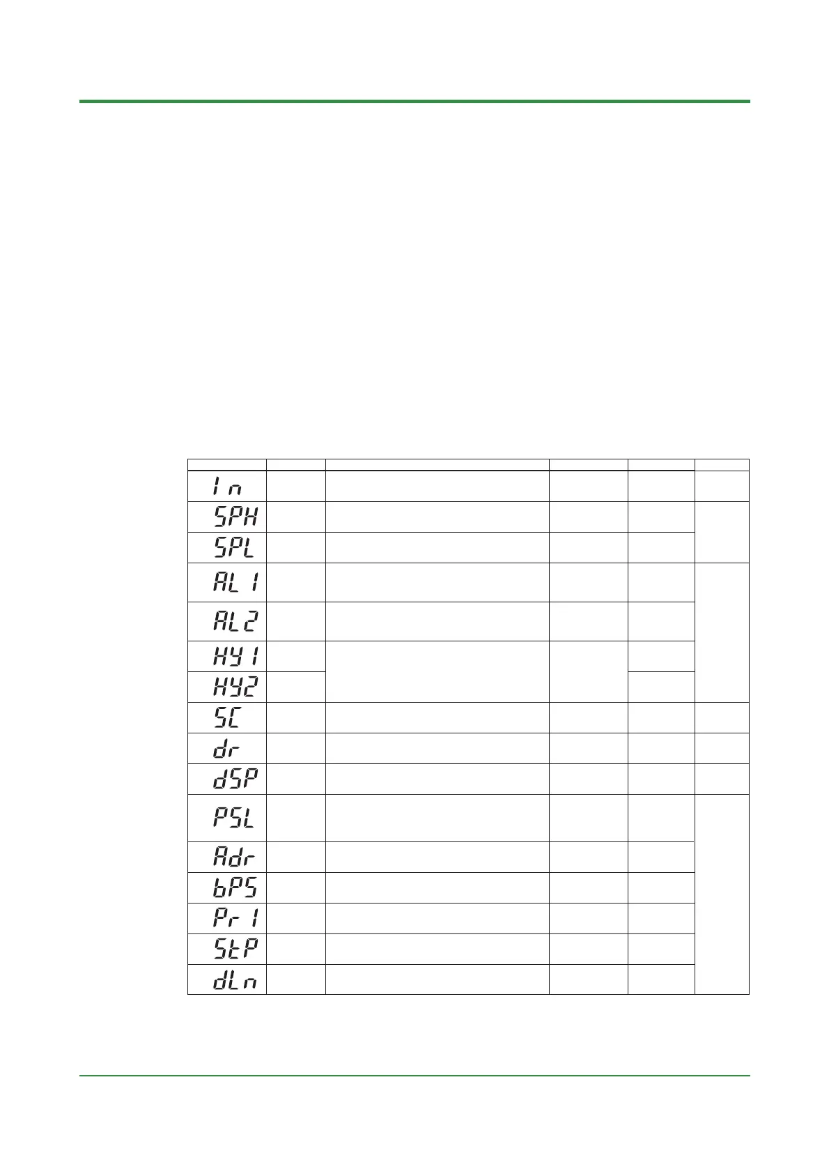
IN
Measured
input type
1 to 7, 12, 13, 15 to 19, 31 to 37, 42, 43, 45 to 48 (See the
measured input range code list.) OFF(0): No input
(If no input type is specified at the time of ordering, you must set the input type.)
OFF(0), or the
input range code
specified with
SPH
Maximum
value of target
setpoint range
(SPL+1°C) to the maximum value of measured input
range; Unit: °C/°F
Maximum value of
measured input
range
SPL
Minimum value
of target
setpoint range
Minimum value of measured input range to (SPH—1°C)
Unit: °C/°F
Minimum value of
measured input
range
AL1
Alarm 1 type
OFF(0), 1 to 22 (See the alarm function list.)
25 (for the heater disconnection alarm /HBA option only)
1
(PV high limit alarm)
AL2
Alarm 2 type
OFF(0), 1 to 22 (See the alarm function list.)
2
(PV low limit alarm)
HY1
Alarm 1
hysteresis
0 to 100% of measured input range span
Unit: °C/°F
0.5% of measured
input range span
HY2
Alarm 2
hysteresis
SC
ON(1): Uses the SUPER function
OFF(0): Does not use SUPER function
Note: Not displayed when on/off control
OFF(0)
DR
Direct/reverse
action
0: Reverse action
1: Direct action
Note: Not displayed for heating/cooling type
0
DSP
Priority of
PV/SP
display
0: Displays PV
1: Displays target setpoint (SP)
0
ADR
Controller
address
1 to 99
However, the number of controllers that can be connected
per host device is 31 at the maximum.
1
BPS
Baud rate
2.4(0): 2400 bps
4.8(1): 4800 bps
9.6(2): 9600 bps
9.6(2)
PRI
Parity
NON(0): Disabled
EVN(1): Even parity
ODD(2): Odd parity
EVN(1)
STP
Stop bit
1 or 2 bits 1 bit
DLN
Data length
7 or 8 bits
• 8 bits when ladder, MODBUS (RTU)
• 7 bits when MODBUS (ASCII)
8 bits
PSL
Protocol
selection
0: PC-link communication
1: PC-link communication with sum check
2: Ladder communication
3: MODBUS in ASCII mode
4: MODBUS in RTU mode
0
Code Name Setting range and unit Default User setting
Reference page
Numbers in ( ) are the parmeter setpoints that apply
when the communication function is used.
Ex. OFF(0), ON(1)
P.4-1
P.5-1
P.5-2
P.4-12
P.4-16
P.4-17
P.6-10
P.4-6
P.
P.5-9
SUPER
function
(3) Setup Parameters: Parameters rarely changed in normal use after once having been set.
 Loading...

