<Toc> <5. Parameters>
5-5
IM 05D01D02-41E 4th Edition: May 31, 2006-00
Parameter
Symbol
Name of Parameter Setting Range and Description Initial Value
User Setting
Target Item
in CD-ROM
Setpoint ramp-up-rate
Setpoint ramp-down-
rate
OFF (0)
0.0% + 1 digit of PV input range span
to 100.0% of PV input range span
Set ramp-up-rate or ramp-down-rate
per hour or minute.
Sets unit in ramp-rate-time unit (TMU).
OFF (0)
OFF (0)
1.0% of PV input range
span
ON/OFF rate detection
band
ON/OFF rate high limit
ON/OFF rate low limit
0.0 to 100.0% of PV input range span
ORL + 1 digit to 105.0% 100.0%
-5.0% to ORH - 1 digit 0.0%
Target setpoint-1
Target setpoint-2
Target setpoint-3
Target setpoint-4
0.0 to 100.0% of PV input range
However, between target setpoint limiter
lower limit (SPL) and upper limit (SPH).
0.0% of PV input range
(UPR)
(DNR)
(ORB)
(ORH)
(ORL)
(1.SP)
(2.SP)
(3.SP)
(4.SP)
Heater burnout current
measurement 2
(HC2)
The current value of the
heater burnout detector
is shown on the display of
the HC1 or HC2 parameter.
Heater burnout current
measurement 1
These are not setpoints.
(HC1)
Heater burnout current
setpoint 2
(HB2)
OFF (0)Heater burnout current
setpoint 1
OFF (0), or 1 to 50 A
(HB1)
On/off rate This is not a setpoint. The moving average (for 5
cycle times) of the control
output is shown.
(OR)
Output high limit
Heating-side output high limit
(in heating/cooling control)
Output low limit
Cooling-side output high limit
(in heating/cooling control)
-5.0 to 105.0%
Heating-side limiter in heating/cooling
control: 0.0 to 105.0% (OL < OH)
-5.0 to 105.0%
Cooling-side limiter in heating/cooling control: 0.0 to
105.0% (OL < OH)
100%
Heating/cooling control:
100.0%
0.0%
Heating/cooling control:
100.0%
ON/OFF control hysteresis
Heating-side/cooling-side
ON/OFF control hysteresis
(in heating/cooling control)
In ON/OFF control: 0.0 to 100.0% of PV input
range span
In heating/cooling control: 0.0 to 100.0%
ON/OFF control: 0.5% of PV
input range span
Heating/cooling control: 0.5%
(OH)
(OL)
(H)
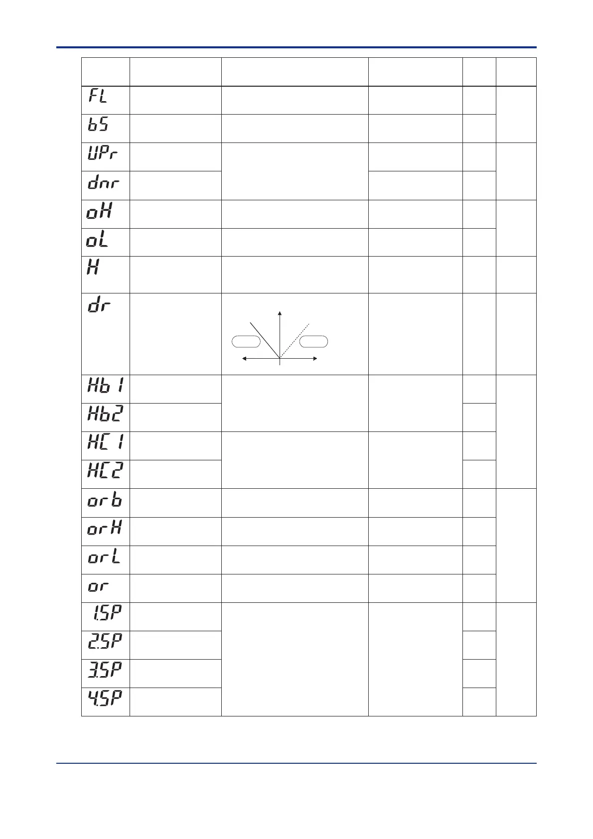
Direct/reverse action
switching
0: reverse action, 1: direct action
0
(DR)
Deviation
(PV-SP)
+
-
Direct
action
Reverse
action
Control output
0%
100%
PV input bias -100.0% to 100.0% of PV input
range span
Used to correct the PV input range.
0.0% of PV input range
span
(BS)
Ref.4.1(4)
Ref.2.1(3)
Ref.2.1(1)
Ref.3.3(5)
Ref.3.3(4)
Ref.4.1(1)
ᎏ
PV input filter OFF (0), 1 to 120 second.
Used when the PV input fluctuates.
OFF (0)
(FL)
Ref.1.1(1)
Artisan Technology Group - Quality Instrumentation ... Guaranteed | (888) 88-SOURCE | www.artisantg.com

 Loading...


