5-6
<Toc> <5. Parameters>
IM 05D01D02-41E 4th Edition: May 31, 2006-00
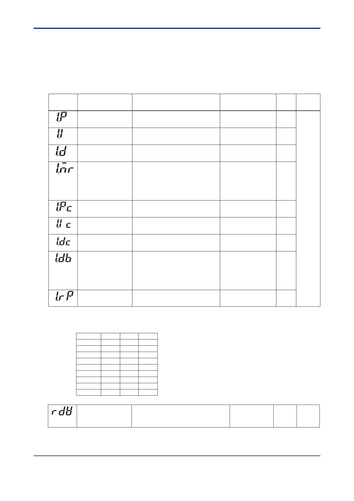
● PID-related Parameters
The following parameters are displayed when “1Gr” is set to PID parameter display number
(PID).
In this case, the corresponding target setpoint is 1.SP (target setpoint-1).
To set PID corresponding to target setpoint 2 to 4, set “2Gr”, “3Gr”, or “4Gr” to PID. The
relevant parameters will then be displayed.
Proportional band/Heating-
side proportional band
(in heating/cooling control)
0.1 to 999.9%
In heating/cooling control: 0.0 to 999.9%
(heating-side ON/OFF control applies when 0.0)
5.0%
Integral time
Heating-side integral time
(in heating/cooling control)
OFF (0), 1 to 6000 second.
OFF (0), 1 to 6000 second.
240 second.
60 second.
Derivative time
Heating-side derivative time
(in heating/cooling control)
Manual reset
-5.0 to 105.0%
(enabled when integral time “1.I” is OFF)
The manual reset value equals the output value
when PV = SP is true.
For example, if the manual reset value is 50%,
the output value is 50% when PV = SP
becomes true.
50.0%
(1.P)
(1.I)
(1.D)
(1.MR)
Parameter
Symbol
Name of Parameter Setting Range and Description Initial Value
User Setting
Target Item
in CD-ROM
Cooling-side integral
time
OFF (0), 1 to 6000 second. 240 second.
60 second.OFF (0), 1 to 6000 second.Cooling-side derivative
time
Deadband
-100.0 to 50.0%
In heating/cooling control, a reagion where
both of the heating- and cooling-side outputs
are presented, or non of them is presented,
can be set.
3.0%
(1.Ic)
(1.Dc)
(1.DB)
Zone PID reference
point-1
100% value of
PV input range
(1.RP)
0.0 to 100.0% of PV input range.
Note that 1.RP ⱕ 2.RP.
Cooling-side
proportional band
0.0 to 999.9%
(Cooling-side ON/OFF control applies when
0.0)
5.0%
(1.Pc)
Ref.4.1(1)
Refer to the table below for recording setpoints when two sets or more of PID parameters
are used.
Parameter n=2 n=3 n=4
n.P
n.I
n.D
n.MR
n.Pc
n.Ic
n.Dc
n.DB
None None
n.RP
Reference deviation
OFF (0), 0.0 to100.0% of PV input range span
Used to select PID constants according to a deviation from
the setpoint. The 4th group of PID constants is used
when the controller fails to keep track of the deviation.
OFF (0)
(RDV)
Ref.4.1(1)
Artisan Technology Group - Quality Instrumentation ... Guaranteed | (888) 88-SOURCE | www.artisantg.com

 Loading...


