IM 05P01D31-11EN page 9/12
Operation Parameters
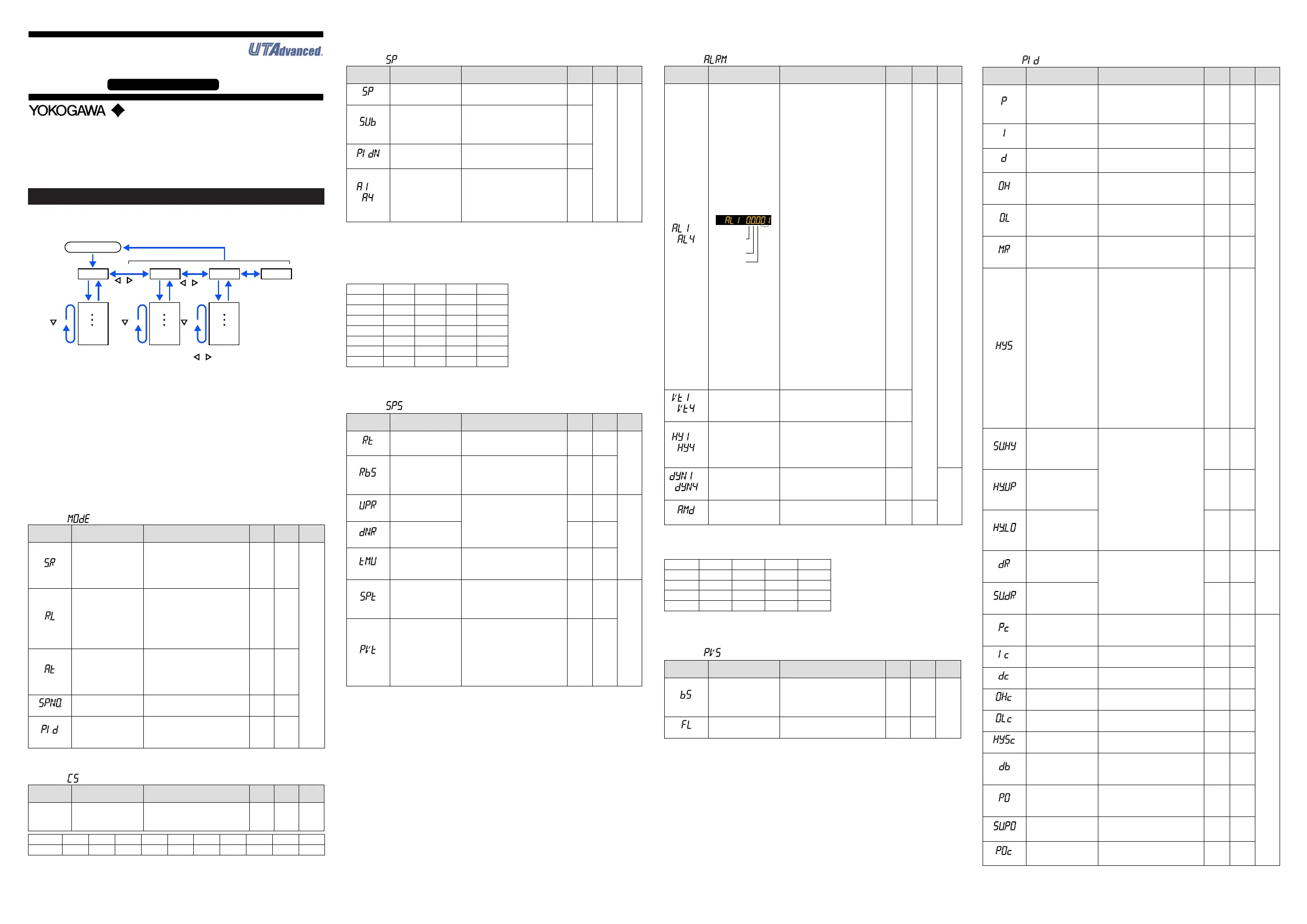
HolddownthePARAMETERkeyorPARAkeyfor3secondstomovefromtheOpera-
tion Display totheOperation Parameter SettingDisplay.PresstheDISPLAYkeyor
DISPkeyoncetoreturntotheOperationDisplay.
Menu
Hold down PARAMETER key or PARA key
for 3 sec.
DISPLAY key
or DISP key
SET/ENTER key
PARAMETER key
or PARA key
key key key
key
key
The parameter groups can be switched using , keys.
Operation Dsipaly
Parameter
Parameter
Parameter
Parameter
Parameter
Parameter
END
Menu
END
Menu END
END
M e nu D i sp la y a nd
Pa r ame t er S et t i ng
Display are changed
in a circular pattern.
Move to the Setup Parameter Setting Display:
Hold down the PARAMETER key or PARA key and the Left arrow key simultaneously
for 3 sec.
Operation for Setting
· Toselecttheparametersettingdisplayedastheinitialvalue,presstheDownarrow
keytomovetothenextparameter.
· Tochangeandsettheparametersetting,presstheSET/ENTERkeytostarttheset-
pointblinking.Theblinkingstateallowsyoutomakechanges(settingmode).Usethe
Up/Down/Left/Rightarrowkeystochangethesetpoint.PresstheSET/ENTERkeyto
registerthesetting.
Notethattherearesomeparameterswhicharenotdisplayeddependingonthemodel
andsufxcodes,controltype(CNT),etc.
n
Operation Mode
Menusymbol:
(MODE)
Parameter
symbol
Name of Parameter Setting Range
Initial
value
User
setting
Display
level
(S.R)
STOP/RUNswitch
STOP: Stop mode
RUN:Runmode
Presetoutput(PO)isgeneratedin
STOP mode.
Default:Notdisplayed.STOP/RUN
switchisassignedtocontactinput.
RUN
EASY
(R.L)
REMOTEL/LOCAL
switch
LCL:Localmode
REM:Remotemode
(Displayedonlyincaseswherethe
communicationisspecied.)
LCL
(AT)
AUTO-tuningswitch
OFF:Disable
1to4:Performauto-tuning.Tuning
resultisstoredinthespeciednum-
beredPID.
R:TuningresultisstoredinthePID
forreferencedeviation.
OFF
(SPNO.)
SPnumberselection
1to4(Dependsonthesetupparam-
eterSPGR.setting.)
1
(PID)
PIDnumber
ThePIDgroupnumberbeingselected
is displayed.
1to4,R:PIDgroupforreference
deviation
1
n
SELECT Parameter
Menusymbol: (CS)
Parameter
symbol
Name of Parameter Setting Range
Initial
value
User
setting
Display
level
Registered
parameter
symbol
SELECTparameter10
to19
Settingrangeofaregisteredparam-
eter.
Fordetails,seeUser'sManual.
0
Table
below
EASY
Parameter n=10 n=11 n=12 n=13 n=14 n=15 n=16 n=17 n=18 n=19
CSn
FortheregistrationofSELECTparameters,seeUser'sManual.
n
SP and Alarm Setpoint Setting Parameter
Menusymbol: (SP)
Parameter
symbol
Name of Parameter Setting Range
Initial
value
User
setting
Display
level
(SP)
Targetsetpoint
0.0to100.0%ofPVinputrange(EU)
(Settingrange:SPLtoSPH)
SPL
Table
below
EASY
(SUB)
Sub-targetsetpoint(in
Two-positiontwo-level
control)
Set the offset from SP.
-100.0to100.0%ofPVinputrange
span(EUS)
0.0%
ofPV
input
range
span
(PIDN)
PIDnumberselection
SetaPIDgroupnumbertouse.
1to4(Dependsonthesetupparam-
eterPIDG.setting.)
1 to 4
to
(A1toA4)
Alarm-1to-4setpoint
SetadisplayvalueofsetpointofPV
alarm,SPalarm,deviationalarm,
outputalarm,orvelocityalarm.
-19999to30000(Setavaluewithinthe
inputrange.)
Decimalpointpositiondependsonthe
input type
0
FortheparameterSP(targetsetpoint),4groupsaredisplayedforthefactorydefault.
Thenumber of groups can be changed by thesetup parameterSPGR. (number of
SPgroups).Forthealarmsetpointparameter,alarm-1to-4aredisplayedforthefac-
torydefault.ThenumberofalarmscanbechangedusingthesetupparameterALNO.
(numberofalarms).TochangethenumberofSPgroupsoralarms,seeUser'sManual.
UsethefollowingtabletorecordSPandalarmsetpoints.
Parameter n=1 n=2 n=3 n=4
SP
SUB
PIDN
A1
A2
A3
A4
n:groupnumber
n
SP-related Setting Parameter
Menusymbol: (SPS)
Parameter
symbol
Name of Parameter Setting Range
Initial
value
User
setting
Display
level
(RT)
Remoteinputratio
SP=RemoteinputxRT+Remote
inputbias
0.001to9.999
1.000
STD
(RBS)
Remoteinputbias
-100.0to100.0%ofPVinputrange
span(EUS)
0.0%
ofPV
input
range
span
(UPR)
SPramp-uprate
UsedtopreventSPfromchanging
suddenly.
Setaramp-uprateorramp-downrate
per hour or minute. Set a time unit
usingtheparameterTMU.
OFF,0.0+1digitto100.0%ofPV
inputrangespan(EUS)
OFF
EASY
(DNR)
SPramp-downrate OFF
(TMU)
SPramp-ratetimeunit
HOUR:Ramp-uprateorramp-down
rate per hour
MIN:Ramp-uprateorramp-down
rate per minute
HOUR
(SPT)
SPtrackingselection
Trackingisperformedwhenthemode
changesfromRemotetoLocal.(The
local setpoint keeps track of the
remotesetpoint.)
OFF,ON
ON
STD
(PVT)
PVtrackingselection
Causesthesetpointtokeeptrackof
thePVsothesetpointautomatically
revertstoitsoriginalvalueatapreset
rateofchange.TheUPR,DNR,and
TMUareusedincombination.Oper-
atingconditions:1)MAN→AUTO,2)
STOP→AUTO,3)Power-on,4)SP
numberchange,5)SPchange
OFF,ON
OFF
n
Alarm Function Setting Parameter
Menusymbol: (ALRM)
Parameter
symbol
Name of Parameter Setting Range
Initial
value
User
setting
Display
level
to
(AL1toAL4)
Alarm-1to4type
Example:Alarm-1
Stand-by
action
Latch action
Energized/
De-energize
Alarm
type
Seta5-digitvalueinthefollowing
order.
[Alarmtype:2digits(seebelow)]+
[Without(0)orWith(1)Stand-byac-
tion]+[Energized(0)orDe-energized
(1)]+[Latchaction(0/1/2/3/4)]
Forlatchaction,seeUser'sManual.
AL1,
AL3:
PVhigh
limit(01)
Without-
Stand-
by
action
(0)
Energi-
zed(0)
Latch
action
(0)
AL2,
AL4:
PVlow
limit(02)
Without
Stand-
by
action
(0)
Energi-
zed(0)
Latch
action
(0)
Table
below
EASY
Alarmtype:2digits
00:Disable
01:PVhighlimit
02:PVlowlimit
03:SPhighlimit
04:SPlowlimit
05:Deviationhighlimit
06:Deviationlowlimit
07:Deviationhighandlowlimits
08:
Deviationwithinhighandlowlimits
09:TargetSPhighlimit
10:TargetSPlowlimit
11:TargetSPdeviationhighlimit
12:TargetSPdeviationlowlimit
13:
TargetSPdeviationhighandlowlimits
14:TargetSPdeviationwithinhigh
and low limits
15:OUThighlimit
16:OUTlowlimit
17:Cooling-sideOUThighlimit
18:Cooling-sideOUTlowlimit
19:AnaloginputPVhighlimit
20:AnaloginputPVlowlimit
27:Feedbackinputhighlimit
28:Feedbackinputlowlimit
29:PVvelocity
30:Faultdiagnosis
31:FAIL
to
(VT1toVT4)
PVvelocityalarmtime
setpoint 1 to 4
0.01to99.59(minute.second) 1.00
to
(HY1toHY4)
Alarm-1to-4hysteresis
Setadisplayvalueofsetpointof
hysteresis.
-19999to30000(Setavaluewithin
theinputrange.)
Decimalpointpositiondependson
the input type.
10
to
(DYN1toDYN4)
Alarm-1to-4On-delay
timer
AnalarmoutputisONwhenthedelay
timerexpiresafterthealarmsetpoint
is reached.
0.00to99.59(minute.second)
0.00
STD
(AMD)
Alarmmode
0:Alwaysactive
1:NotactiveinSTOPmode
2:NotactiveinSTOPorMANmode
0
Forthealarmfunctionsettingparameter,4alarmsaredisplayedforthefactorydefault.
The number of alarms canbe changed bythe setup parameter ALNO. (number of
alarms).Tochangethenumberofalarms,seeUser'sManual.
Parameter n=1 n=2 n=3 n=4
ALn
VTn
HYn
DYNn
n:alarmnumber
n
PV-related Setting Parameter
Menusymbol: (PVS)
Parameter
symbol
Name of Parameter Setting Range
Initial
value
User
setting
Display
level
(BS)
PVinputbias
-100.0to100.0%ofPVinputrange
span(EUS)
0.0%
ofPV
input
range
span
EASY
(FL)
PVinputlter OFF,1to120s OFF
n
PID Setting Parameter
Menusymbol: (PID)
Parameter
symbol
Name of Parameter Setting Range
Initial
value
User
setting
Display
level
(P)
Proportionalband
Heating-sideproportion-
alband(inHeating/cool-
ingcontrol)
0.0to999.9%
When0.0%isset,itoperatesas
0.1%.
Heating-sideON/OFFcontrolapplies
when0.0%inHeating/coolingcontrol
5.0%
EASY
(I)
Integraltime
Heating-sideintegraltime
(inHeating/coolingcontrol)
OFF:Disable
1to6000s
240s
(D)
Derivativetime
Heating-sidederivativetime
(inHeating/coolingcontrol)
OFF:Disable
1to6000s
60s
(OH)
Controloutputhighlimit
Heating-sidecontrol
outputhighlimit(in
Heating/coolingcontrol)
-4.9to105.0%,(OL<OH)
InHeating/coolingcontrol:0.1to
105.0%(OL<OH)
100.0%
(OL)
Controloutputlowlimit
Heating-sidecontrol
outputlowlimit(inHeat-
ing/coolingcontrol)
-5.0to104.9%,(OL<OH),SD:Tight
shut
InHeating/coolingcontrol:0.0to
104.9%(OL<OH)
0.0%
(MR)
Manual reset
EnabledwhenintegraltimeisOFF.
Themanualresetvalueequalsthe
outputvaluewhenPV=SP.
-5.0to105.0%
50.0%
(HYS)
Hysteresis(inON/OFF
control, Position
proportional control, or
Two-positiontwo-level
control)
Heating-sideON/OFF
controlhysteresis(in
Heating/coolingcontrol)
InON/OFFcontrolorTwo-position
two-levelcontrol:0.0to100.0%of
PVinputrangespan(EUS)
InHeating/coolingcontrolorPosition
proportionalcontrol:0.0to100.0%
In
ON/OFF
control
or
Two-
position
two-level
control:
0.5%of
PVinput
range
span
In Heat-
ing/
cooling
control
or
Position
proportional
control:
0.5%
(SU.HY)
Sub-hysteresis(in
Two-positiontwo-level
control)
0.0to100.0%ofPVinputrange
span(EUS)
0.5%
ofPV
input
range
span
(HY.UP)
Upper-sidehysteresis
(inON/OFFcontrol)
0.5%
ofPV
input
range
span
(HY.LO)
Lower-sidehysteresis
(inON/OFFcontrol)
0.5%
ofPV
input
range
span
(DR)
Direct/reverseaction
switch
RVS:Reverseaction
DIR:Directaction
RVS
STD
(SU.DR)
Sub-direct/reverse
actionswitch(inTwo-
positiontwo-level
control)
DIR
(Pc)
Cooling-sidepropor-
tionalband
0.0to999.9%
(Cooling-sideON/OFFcontrol
applieswhen0.0%inHeating/cool-
ingcontrol)
5.0%
EASY
(Ic)
Cooling-sideintegral
time
OFF:Disable
1to6000s
240s
(Dc)
Cooling-sidederivative
time
OFF:Disable
1to6000s
60s
(OHc)
Cooling-sidecontrol
outputhighlimit
0.1to105.0%,(OLc<OHc) 100.0%
(OLc)
Cooling-sidecontrol
output low limit
0.0to104.9%,(OLc<OHc) 0.0%
(HYSc)
Cooling-sideON/OFF
control hysteresis
0.0to100.0% 0.5%
(DB)
Outputdeadband(in
Heating/coolingcontrol
or Position proportional
control)
InHeating/coolingcontrol:-100.0to
50.0%
InPositionproportionalcontrol:1.0
to10.0%
3.0%
(PO)
Preset output
Heating-sidepreset
output(inHeating/cool-
ingcontrol)
InSTOPmode,xedcontroloutput
canbegenerated.InPositionpropor-
tionalcontrol,Valveopeningcanbe
set;-5.0to105.0%
0.0%
(SU.PO)
Sub-presetoutput(in
Two-positiontwo-level
control)
InSTOPmode,xedsub-control
outputcanbegenerated.
0%,100%
0%
(POc)
Cooling-sidepreset
output
InSTOPmode,cooling-sidexed
controloutputcanbegenerated.
-5.0to105.0%
0.0%
ForthePIDsettingparameter,4groupsaredisplayedforthefactorydefault.
ThenumberofgroupscanbechangedbythesetupparameterPIDG.(numberofPID
groups).TochangethenumberofPIDgroups,seeUser'sManual.
Operation
Guide
UT35A/UT32A
Digital Indicating Controllers
Operation Guide
This operation guide describes the functions of parameters briefly. The parameter
symbols listed are in the order shown on the display in each group of menu symbols.
In addition, each parameter table has a “User Setting” column, where you can record
your setpoints when setting them in the controller. The scrolling guide is displayed on
PV display in the Parameter Setting Display. This guide can be turned on/off with
the Fn key.
Yokogawa Electric Corporation
Parameters

 Loading...


