IM 05P01D31-11EN page 10/12
IfyouareusingtwoormoregroupsofPIDparameters,usethefollowingtabletorecordtheirsettingvalues.
Parameter n=2 n=3 n=4 R
P
I
D
OH
OL
MR
HYS
SU.HY
HY.UP
HY.LO
DR
SU.DR
Pc
Ic
Dc
OHc
OLc
HYSc
DB
PO
SU.PO
POc
n:groupnumber
n
Tuning Parameter
Menusymbol:
(TUNE)
Parameter
symbol
Name of Parameter Setting Range
Initial
value
User
setting
Display
level
(SC)
Super function
OFF:Disable
1:Overshootsuppressingfunction
(normalmode)
2:Huntingsuppressingfunction
(stablemode)
Enablestoanswerthewider
characteristicchangescompared
with response mode.
3:Huntingsuppressingfunction
(responsemode)
Enablesquickfollow-upandshort
convergingtimeofPVforthe
changedSP.
4:Overshootsuppressingfunction
(strongsuppressingmode)
Note:Setpoints2and3mustbe
usedinPIDcontrolorPIcontrol.
Disabledinthefollowingcontrols:
1)ON/OFFcontrol,2)PDcontrol,
3)Pcontrol,4)Heating/cooling
control.
Donotusethefunctionforthe
control processes with response
suchasoworpressurecontrol.
OFF EASY
(AT.TY)
Auto-tuningtype
0:Normal
1:Stability
0
STD
(AR)
Anti-resetwindup
(excessintegration
prevention)
AUTO,50.0to200.0% AUTO
(OPR)
Outputvelocitylimiter
OFF:Disable
0.1to100.0%/s
OFF
(MPON)
Manual preset output
numberselection
SelecttheoutputusedinMANmode
whenswitchedfromAUTOtoMAN
mode.
OFF:HoldthecontroloutputinAUTO
mode(bumpless)
1:Usemanualpresetoutput1(output
bump)
2:Usemanualpresetoutput2(output
bump)
3:Usemanualpresetoutput3(output
bump)
4:Usemanualpresetoutput4(output
bump)
5:Usemanualpresetoutput5(output
bump)
OFF
to
(MPO1toMPO5)
Manual preset output 1
to 5
-5.0to105.0%
However,outputislimitedtothe
outputhighlimitandlowlimit.
0.0%
Table
below
Usethefollowingtabletorecordthemanualpresetoutputsettingvalue.
Parameter n=1 n=2 n=3 n=4 n=5
MPOn
n
Zone Control Parameter
Menusymbol: (ZONE)
Parameter
symbol
Name of Parameter Setting Range
Initial
value
User
setting
Display
level
to
(RP1toRP3)
Referencepoint1to3
Set reference points at which switch-
ingiscarriedoutbetweengroupsof
PIDconstantsaccordingtothegiven
temperaturezone.
0.0to100.0%ofPVinputrange(EU)
(RP1≤RP2≤RP3)
100.0%
ofPV
input
range
Table
below
STD
(RHY)
ZonePIDswitching
hysteresis
Hysteresiscanbesetforswitchingat
a reference point.
0.0to10.0%ofPVinputrangespan
(EUS)
0.5%
ofPV
input
range
span
(RDV)
Referencedeviation
SetadeviationfromSP.ThePIDfor
referencedeviationisusedifthere
isalargerdeviationthanthepreset
referencedeviation.
OFF:Disable
0.0+1digitto100.0%ofPVinput
rangespan(EUS)
OFF
ForZonecontrol,setthesetupparameterZON(zonePIDselection)toZonePIDse-
lection.
Usethefollowingtabletorecordthereferencepointsettingvalue.
Parameter n=1 n=2 n=3
RPn
n
P Parameter (for Ladder Program)
Menusymbol: (PPAR)
Parameter
symbol
Name of Parameter Setting Range
Initial
value
User
setting
Display
level
to
(P01toP10)
P01toP10parameter
-19999to30000(Setadecimalpoint
positionusingLL50AParameterSet-
tingSoftware.)
0
Table
below
STD
Parameter n=01 n=02 n=03 n=04 n=05 n=06 n=07 n=08 n=09 n=10
Pn
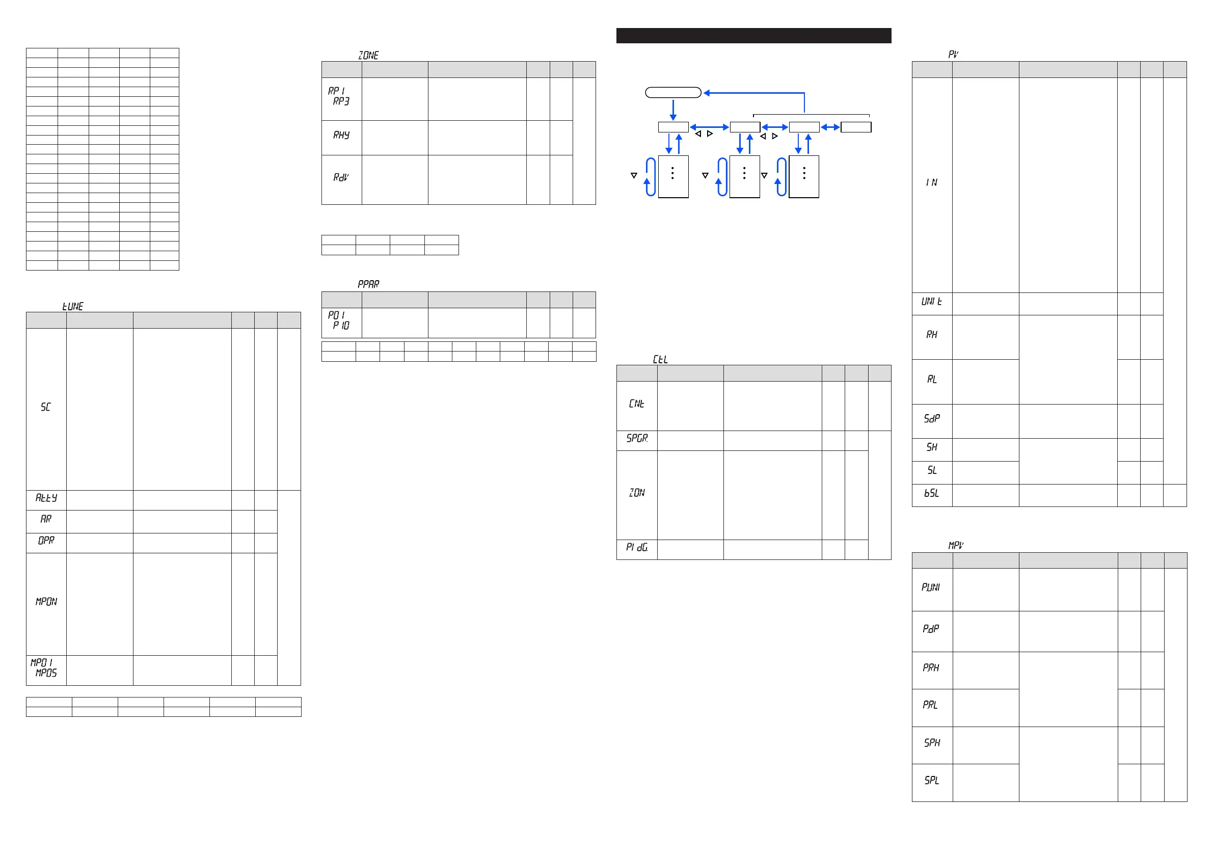
Setup Parameters
HolddownthePARAMETERkeyorPARAkeyandLeftarrowkeysimultaneouslyfor3
secondstomovefromtheOperationDisplayorOperationParameterSettingDisplayto
theSetupParameterSettingDisplay.
PresstheDISPLAYkeyorDISPkeyoncetoreturntotheOperationDisplay.
Menu
DISPLAY key
or DISP key
SET/ENTER key
PARAMETER key
or PARA key
key key key
key
key
Operation Dsipaly
Parameter
Parameter
Parameter
Parameter
Parameter
Parameter
END
Menu
END
Menu END
END
M e n u Di sp la y an d
Pa ra m et e r Set ti n g
Display are changed
in a circular pattern.
Move to the Operation Parameter Setting Display:
Hold down the PARAMETER key or PARA key for 3 sec.
Hold down PARAMETER key or PARA key and
Left arrow key simultaneously for 3 sec.
Operation for Setting
· Toselecttheparametersettingdisplayedastheinitialvalue,presstheDownarrow
keytomovetothenextparameter.
· Tochangeandsettheparametersetting,presstheSET/ENTERkeytostarttheset-
pointblinking.Theblinkingstateallowsyoutomakechanges(settingmode).Usethe
Up/Down/Left/Rightarrowkeystochangethesetpoint.PresstheSET/ENTERkeyto
registerthesetting.
NotethattherearesomeparameterswhicharenotdisplayeddependingontheModel
andSufxcodes,controltype(CNT),etc.
n
Control Function Setting Parameter
Menusymbol: (CTL)
Parameter
symbol
Name of Parameter Setting Range
Initial
value
User
setting
Display
level
(CNT)
Controltype
PID:PIDcontrol
ONOF:ON/OFFcontrol(1pointof
hysteresis)
ONOF2:ON/OFFcontrol(2pointsof
hysteresis)
2P2L:Two-positiontwo-levelcontrol
H/C:Heating/coolingcontrol
PID EASY
(SPGR.)
NumberofSPgroups
SetanumberofSPgroupstouse.
1 to 4
4
STD
(ZON)
ZonePIDselection
Ifsetto“SPgroupnumberselection,”
allowsPIDconstantstobeselected
foreachSPgroup.
Ifsetto“ZonePIDselection,”
automaticallyselectsPIDconstants
accordingtotherangesetinthe
Referencepoint.
0:SPgroupnumberselection1
1:
ZonePIDselection(selectionbyPV)
2:ZonePIDselection(selectionby
targetSP)
3:SPgroupnumberselection2
4:
ZonePIDselection(selectionbySP)
0
(PIDG.)
NumberofPIDgroups
SetanumberofPIDgroupstouse.
1 to 4
4
n
PV Input Setting Parameter
Menusymbol: (PV)
Parameter
symbol
Name of Parameter Setting Range
Initial
value
User
setting
Display
level
(IN)
PVinputtype
OFF:Disable
K1:-270.0to1370.0
0
C/-450.0to2500.0
0
F
K2:-270.0to1000.0
0
C/-450.0to2300.0
0
F
K3:-200.0to500.0
0
C/-200.0to1000.0
0
F
J:-200.0to1200.0
0
C/-300.0to2300.0
0
F
T1:-270.0to400.0
0
C/-450.0to750.0
0
F
T2:0.0to400.0
0
C/-200.0to750.0
0
F
B:0.0to1800.0
0
C/32to3300
0
F
S:0.0to1700.0
0
C/32to3100
0
F
R:0.0to1700.0
0
C/32to3100
0
F
N:-200.0to1300.0
0
C/-300.0to2400.0
0
F
E:-270.0to1000.0
0
C/-450.0to1800.0
0
F
L:-200.0to900.0
0
C/-300.0to1600.0
0
F
U1:-200.0to400.0
0
C/-300.0to750.0
0
F
U2:0.0to400.0
0
C/-200.0to1000.0
0
F
W:0.0to2300.0
0
C/32to4200
0
F
PL2:0.0to1390.0
0
C/32.0to2500.0
0
F
P2040:0.0to1900.0
0
C/32to3400
0
F
WRE:0.0to2000.0
0
C/32to3600
0
F
JPT1:-200.0to500.0
0
C/-300.0to1000.0
0
F
JPT2:-150.0to150.0
0
C/-200.0to300.0
0
F
PT1:-200.0to850.0
0
C/-300.0to1560.0
0
F
PT2:-200.0to500.0
0
C/-300.0to1000.0
0
F
PT3:-150.00to150.00
0
C/-200.0to300.0
0
F
0.4-2V:0.400to2.000V
1-5V:1.000to5.000V
4-20:4.00to20.00mA
0-2V:0.000to2.000V
0-10V:0.00to10.00V
0-20:0.00to20.00mA
-1020:-10.00to20.00mV
0-100:0.0to100.0mV
OFF
EASY
(UNIT)
PVinputunit
-:Nounit,C:DegreeCelsius
-:Nounit,--:Nounit,---:Nounit,
F:DegreeFahrenheit
C
(RH)
MaximumvalueofPV
inputrange
Dependsontheinputtype.
-Fortemperatureinput-
Setthetemperaturerangethatis
actuallycontrolled.(RL<RH)
-Forvoltage/currentinput-
Settherangeofavoltage/current
signalthatisapplied.
Thescaleacrosswhichthevoltage/
currentsignalisactuallycontrolled
shouldbesetusingthemaximum
valueofinputscale(SH)andmini-
mumvalueofinputscale(SL).
(Inputisalways0%whenRL=RH.)
Depends
on the
input type
(RL)
MinimumvalueofPV
inputrange
Depends
on the
input type
(SDP)
PVinputscaledecimal
point position
0:Nodecimalplace
1: One decimal place
2: Two decimal places
3: Three decimal places
4: Four decimal places
Depends
on the
input type
(SH)
MaximumvalueofPV
input scale
-19999to30000,(SL<SH),
|SH-SL|≤30000
Depends
on the
input type
(SL)
MinimumvalueofPV
input scale
Depends
on the
input type
(BSL)
PVinputburnoutaction
OFF:Disable
UP:Upscale
DOWN:Downscale
Depends
on the
input type
STD
W:W-5%Re/W-26%Re(HoskinsMfg.Co.).ASTME988,WRE:W97Re3-W75Re25
n
Input Range, SP Limiter Setting Parameter
Menusymbol: (MPV)
Parameter
symbol
Name of Parameter Setting Range
Initial
value
User
setting
Display
level
(P.UNI)
ControlPVinputunit
-:Nounit
C:DegreeCelsius
-:Nounit
--:Nounit
---:Nounit
F:DegreeFahrenheit
Same
asPV
input
unit
STD
(P.DP)
ControlPVinputdecimal
point position
0:Nodecimalplace
1: One decimal place
2: Two decimal places
3: Three decimal places
4: Four decimal places
1
(P.RH)
Maximumvalueof
controlPVinputrange
-19999to30000,(P.RL<P.RH),
|P.RH-P.RL|≤30000
Depends
on the
input type
(P.RL)
Minimumvalueofcontrol
PVinputrange
Depends
on the
input type
(SPH)
SPhighlimit
0.0to100.0%ofPVinputrange(EU),
(SPL<SPH)
100.0%
ofPV
input
range
(SPL)
SP low limit
0.0%
ofPV
input
range
 Loading...


