IM 05P01D31-11EN page 11/12
n
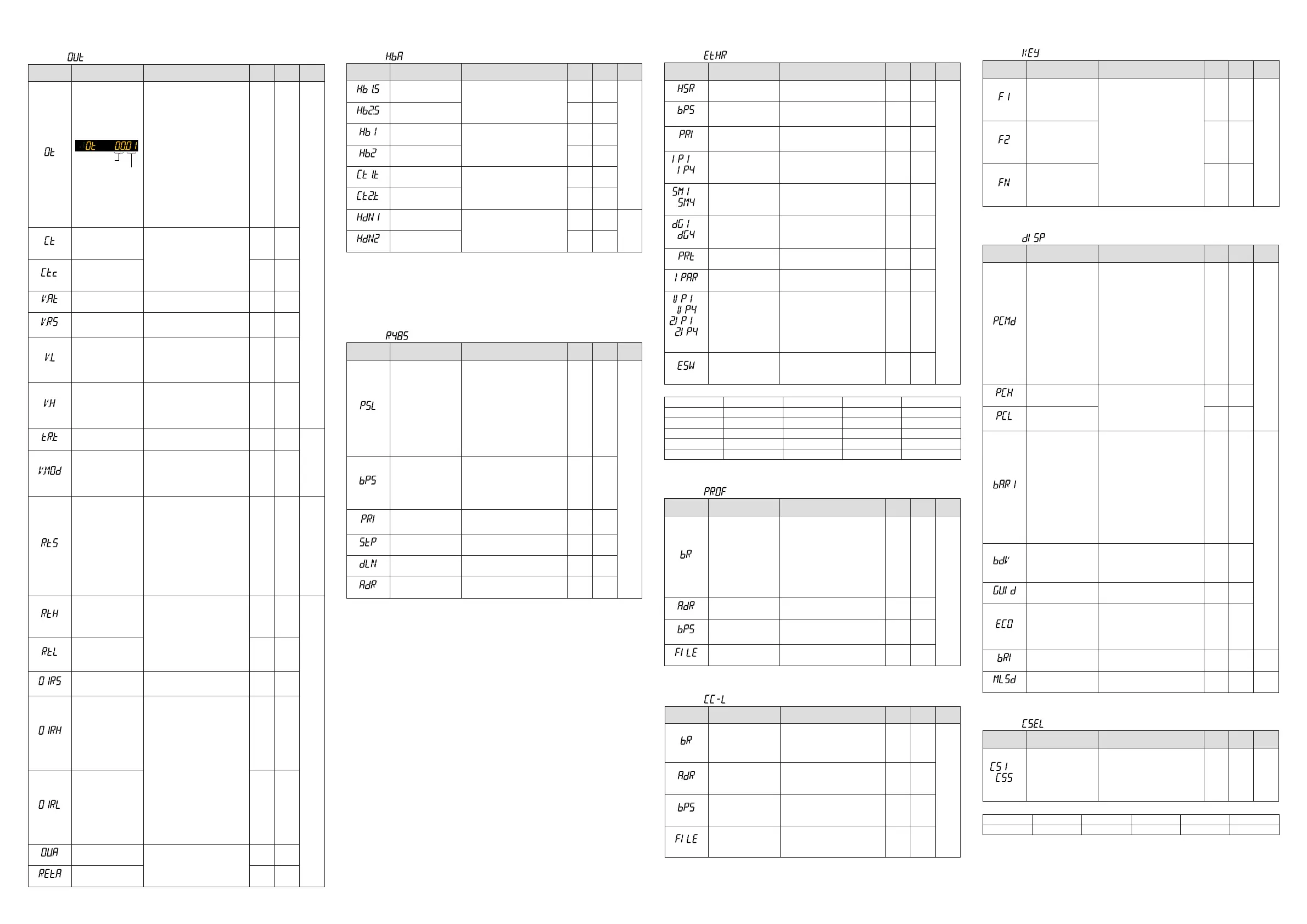
Output Setting Parameter
Menusymbol: (OUT)
Parameter
symbol
Name of Parameter Setting Range
Initial
value
User
setting
Display
level
(OT)
Output type selection
Upper two
digits
Lower two
digits
ControloutputorHeating-sidecontrol
output(Lowertwodigits)
00:OFF
01:OUTterminals(voltagepulse)
02:OUTterminals(current)
03:OUTterminals(relay)
06:OUT2terminals(relay)
07:RET/OUT2terminals(voltage
pulse)
08:RET/OUT2terminals(current)
Cooling-sidecontroloutput(Upper
twodigits)
00:OFF
01:OUTterminals(voltagepulse)
02:OUTterminals(current)
03:OUTterminals(relay)
06:OUT2terminals(relay)
07:RET/OUT2terminals(voltage
pulse)
08:RET/OUT2terminals(current)
Standard
type:
00.03
Heating/
cooling
type:
06.03
EASY
(CT)
Controloutputcycletime
Heating-sidecontrol
outputcycletime(in
Heating/coolingcontrol)
0.5to1000.0s
30.0s
(CTc)
Cooling-sidecontrol
output cycle time
30.0s
(V.AT)
Automaticvalveposition
adjustment
OFF:Stopautomaticadjustment
ON:Startautomaticadjustment
OFF
(V.RS)
Valvepositionsetting
reset
SettingV.RStoONresetsthevalve
adjustmentsettingsandcausesthe
indication“V.RS”toblink.
OFF
(V.L)
Fully-closedvalveposi-
tionsetting
PressingtheSET/ENTERkeywith
valvepositionsettothefully-closed
positionbyDownarrowkeycauses
theadjustedvaluetobestored.When
V.Ladjustmentiscomplete,V.Lstops
blinking.
-
(V.H)
Fully-openedvalveposi-
tionsetting
PressingtheSET/ENTERkeywith
valvepositionsettothefully-opened
positionbyUparrowkeycausesthe
adjustedvaluetobestored.WhenV.H
adjustmentiscomplete,V.Hstops
blinking
-
(TR.T)
Valvetravelingtime 5to300s 60s
STD
(V.MOD)
Valveadjustingmode
0:Valvepositionfeedbacktype
1:Valvepositionfeedbacktype
(movestotheestimatingtypeifa
feedbackinputerrororbreakoc-
curs.)
2:Valvepositionestimatingtype
0
(RTS)
Retransmissionoutput
typeofRET
OFF:Disable
PV1:PV
SP1: SP
OUT1:OUT(Valveopening:0to100
%inPositionproportionalcontrol)
LPS:15VDClooppowersupply
TSP1:TargetSP
HOUT1:Heating-sideOUT
COUT1:Cooling-sideOUT
MV1:Positionproportionaloutput
(internalcomputedvalue)
PV:PVterminalsanaloginput
PV1 EASY
(RTH)
Maximumvalueof
retransmission output
scaleofRET
WhenRTS=PV1,SP1,TSP1,PV
RTL+1digitto30000
-19999toRTH-1digit
Decimalpointposition:
WhenRTS=PV1,SP1,orTSP1,
decimal point position is same as
thatofPVinput.
WhenRTS=PV,decimalpointposition
issameasthatofPVinputscale.
100%
ofPV
input
range
STD
(RTL)
Minimumvalueof
retransmission output
scaleofRET
0%
ofPV
input
range
(O1RS)
Retransmissionoutput
typeofOUTcurrent
output
SameasRTS
OFF
(O1RH)
Maximumvalueof
retransmission output
scaleofOUTcurrent
output
WhenO1RS=PV1,SP1,TSP1,PV,
O1RL+1digitto30000
-19999toO1RH-1digit
Decimalpointposition:
WhenO1RS=PV1,SP1,orTSP1,
decimal point position is same as
thatofPVinput.
WhenO1RS=PV,decimalpointposi-
tionissameasthatofPVinput
scale.
-
(O1RL)
Minimumvalueof
retransmission output
scaleofOUTcurrent
output
-
(OU.A)
OUTcurrentoutput
range
4-20:4to20mA
0-20:0to20mA
20-4:20to4mA
20-0:20to0mA
4-20
(RET.A)
RETcurrentoutput
range
4-20
n
Heater Break Alarm Setting Parameter
Menusymbol: (HBA)
Parameter
symbol
Name of Parameter Setting Range
Initial
value
User
setting
Display
level
(HB1.S)
Heaterbreakalarm-1
function selection
0:Heatercurrentmeasurement
1:Heaterbreakalarm(Heating-side)
2:Cooling-sideheaterbreakalarm
1
EASY
(HB2.S)
Heaterbreakalarm-2
function selection
1
(HB1)
Heaterbreakalarm-1
current setpoint
OFF,0.1to300.0Arms
OFF
(HB2)
Heaterbreakalarm-2
current setpoint
OFF
(CT1.T)
CT1
coilwindingnumberratio
1to3300
800
(CT2.T)
CT2
coilwindingnumberratio
800
(HDN1)
Heaterbreakalarm-1
On-delaytimer
0.00to99.59(m.s)
0.00
STD
(HDN2)
Heaterbreakalarm-2
On-delaytimer
0.00
IncaseswherethecurrenttransformersmanufacturedbyU.R.D.Co.,Ltdareused,set
thefollowingvalueforthecoilwindingnumberratio.
CTL-6-S-H:800
CTL-12L-30:3000
n
RS-485 Communication Setting Parameter (UT35A: E3-terminal
Area, UT32A: E1-terminal Area)
Menusymbol: (R485)
Parameter
symbol
Name of Parameter Setting Range
Initial
value
User
setting
Display
level
(PSL)
Protocol selection
PCL:PClinkcommunication
PCLSM:PClinkcommunication(with
checksum)
LADR:Laddercommunication
CO-M:Coordinatedmasterstation
CO-S:Coordinatedslavestation
MBASC:Modbus(ASCII)
MBRTU:Modbus(RTU)
CO-S1:Coordinatedslavestation
(Loop-1mode)
CO-S2:Coordinatedslavestation
(Loop-2mode)
P-P:Peer-to-peercommunication
MBRTU
EASY
(BPS)
Baud rate
600:600bps
1200:1200bps
2400:2400bps
4800:4800bps
9600:9600bps
19200:19.2kbps
38400:38.4kbps
19200
(PRI)
Parity
NONE:None
EVEN:Even
ODD:Odd
EVEN
(STP)
Stopbit 1:1bit,2:2bits 1
(DLN)
Datalength 7:7bits,8:8bits 8
(ADR)
Address 1to99 1
■
Ethernet Communication Setting Parameter (E3-terminal Area)
Menusymbol: (ETHR)
Parameter
symbol
Name of Parameter Setting Range
Initial
value
User
setting
Display
level
(HSR)
High-speedresponse
mode
OFF,1to8 1
EASY
(BPS)
Baud rate
9600:9600bps
19200:19.2kbps
38400:38.4kbps
38400
(PRI)
Parity
NONE:None
EVEN:Even
ODD:Odd
EVEN
to
(IP1toIP4)
IP address 1 to 4
0to255
Initialvalue:
(IP1).(IP2).(IP3).(IP4)=
(192).(168).(1).(1)
See left
Table
below
to
(SM1toSM4)
Subnetmask1to4
0to255
Initialvalue:
(SM1).(SM2).(SM3).(SM4)=
(255).(255).(255).(0)
See left
Table
below
to
(DG1toDG4)
Defaultgateway1to4
0to255
Initialvalue:
(DG1).(DG2).(DG3).(DG4)=
(0).(0).(0).(0)
See left
Table
below
(PRT)
Portnumber 502,1024to65535 502
(IPAR)
IP access restriction OFF:Disable,ON:Enable OFF
to
,
to
(1.IP1to1.IP4,
2.IP1to2.IP4)
PermittedIPaddress1-1
to1-4
PermittedIPaddress2-1
to2-4
0to255
Initialvalue:
(1.IP1).(1.IP2).(1.IP3).(1.IP4)=
(255).(255).(255).(255)
(2.IP1).(2.IP2).(2.IP3).(2.IP4)=
(255).(255).(255).(255)
See left
Table
below
(ESW)
Ethernetsettingswitch
Settingthisparameterto“ON”
enablestheEthernetcommunication
parametersettings.
OFF,ON
OFF
UsethefollowingtabletorecordEthernetcommunicationsettingvalue.
Parameter n=1 n=2 n=3 n=4
IPn
SMn
DGn
1.IPn
2.IPn
n
PROFIBUS-DP Communication Setting Parameter (E3-terminal Area)
Menusymbol: (PROF)
Parameter
symbol
Name of Parameter Setting Range
Initial
value
User
setting
Display
level
(BR)
Baud rate
9.6K:9.6kbps
19.2K:19.2kbps
93.75K:93.75kbps
187.5K:187.5kbps
0.5M:0.5Mbps
1.5M:1.5Mbps
3M:3Mbps
6M:6Mbps
12M:12Mbps
AUTO
45.45K:45.45kbps
AUTO
EASY
(ADR)
Address 0to125 3
(BPS)
Baud rate
9600:9600bps
19200:19.2kbps
38400:38.4kbps
38400
(FILE)
Prolenumber 0to3 0
n
CC-Link Communication Setting Parameter (E3-terminal Area)
Menusymbol: (CC-L)
Parameter
symbol
Name of Parameter Setting Range
Initial
value
User
setting
Display
level
(BR)
Baud rate
156K:156kbps
625K:625kbps
2.5K:2.5kbps
5M:5Mbps
10M:10Mbps
10M
EASY
(ADR)
Address 1 to 64 1
(BPS)
Baud rate
9600:9600bps
19200:19.2kbps
38400:38.4kbps
38400
(FILE)
Prolenumber 0to3
0
■KeyActionSettingParameter
Menusymbol: (KEY)
Parameter
symbol
Name of Parameter Setting Range
Initial
value
User
setting
Display
level
(F1)
Userfunctionkey-1
actionsetting
OFF:Disable
A/M:AUTO/MANswitch
R/L1:REM/LCLswitch
S/R:STOP/RUNswitch
AUTO:SwitchtoAUTO
MAN:SwitchtoMAN
REM1:SwitchtoREM
LCL1:SwitchtoLCL
STOP: Switch to STOP
RUN:SwitchtoRUN
AT:Auto-tuning
LTUP:LCDbrightnessUP
LTDN:LCDbrightnessDOWN
BRI:AdjustLCDbrightness
LCD:LCDbacklightON/OFFswitch
LAT:Latchrelease
PID:PIDtuningswitch
OFF
EASY
(F2)
Userfunctionkey-2
actionsetting
OFF
(Fn)
Userfunctionkey-n
actionsetting
PID
■DisplayFunctionSettingParameter
Menusymbol: (DISP)
Parameter
symbol
Name of Parameter Setting Range
Initial
value
User
setting
Display
level
(PCMD)
ActivecolorPVdisplay
switch
0:Fixedinwhite
1:Fixedinred
2:Linktoalarm1(AlarmOFF:white,
AlarmON:red)
3:Linktoalarm1(AlarmOFF:red,
AlarmON:white)
4:Linktoalarm1or2(AlarmOFF:
white,AlarmON:red)
5:Linktoalarm1or2(AlarmOFF:
red,AlarmON:white)
6:PVlimit(Withinrange:white,Out
ofrange:red)
7:PVlimit(Withinrange:red,Outof
range:white)
8:SPdeviation(Withindeviation:
white,Outofdeviation:red)
9:SPdeviation(Withindeviation:red,
Outofdeviation:white)
0
EASY
(PCH)
PVcolorchangehigh
limit
SetadisplayvaluewheninPVlimit
orSPdeviation.
-19999to30000(Setavaluewithin
theinputrange.)
Decimalpointpositiondependson
the input type.
0
(PCL)
PVcolorchangelowlimit 0
(BAR1)
Bar-graphdisplayregis-
tration
0:Disable
1:
OUT,Heating-sideOUT,Internalvalue
in Position proportional control
2:Cooling-sideOUT
3:PV
4: SP
5:Deviation
6to16:Disable
17:Feedbackinput(valveopening)
18:PVterminalsanaloginput
5
(Heating
/cooling
type:1)
STD
(BDV)
Bar-graphdeviation
displayband
0.0to100.0%ofPVinputrangespan
(EUS)
10.0%
ofPV
input
range
span
(GUID)
GuidedisplayON/OFF OFF:Nondisplay,ON:Display ON
(ECO)
Economymode
OFF:Disable
1:EconomymodeON(Allindications
exceptPVdisplayOFF)
2:EconomymodeON(Allindications
OFF)
3:Brightness10%(wholeindication)
OFF
(BRI)
Brightness (Dark)1to5(Bright) 3 EASY
(MLSD)
Leastsignicantdigital
maskofPVdisplay
OFF:Withleastsignicantdigit
ON:Withoutleastsignicantdigit
OFF STD
■SELECTDisplaySettingParameter
Menusymbol: (CSEL)
Parameter
symbol
Name of Parameter Setting Range
Initial
value
User
setting
Display
level
to
(CS1toCS5)
SELECTDisplay-1to-5
registration
Registertheoperationparameter
(excepttheOperaitonMode)thatis
frequentlymodiedtodisplayitinthe
OperationDisplay.
OFF,2301to5000
Forthesettingrange,seeUser's
Manual.
OFF STD
UsethefollowingtabletorecordSELECTDsipalysettingvalue.
Parameter n=1 n=2 n=3 n=4 n=5
CSn

 Loading...


