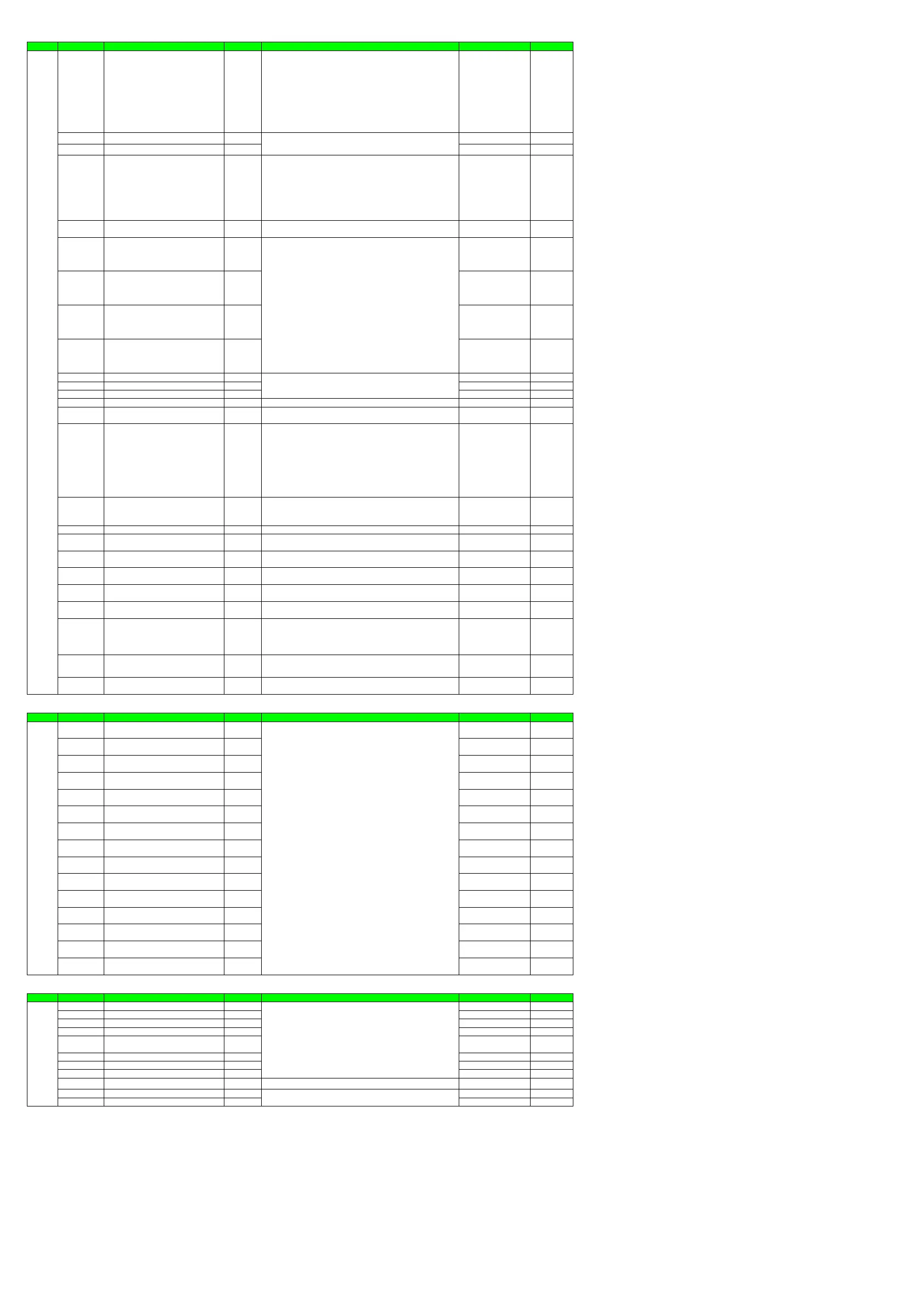
Display Function Setting
Menu Symbol Name Display level Setting range Initial value User setting
DISP PCMD Active color PV display switch EASY
0: Fixed in white
1: Fixed in red
2: Link to alarm 1 (Alarm OFF: white, Alarm ON: red)
3: Link to alarm 1 (Alarm OFF: red, Alarm ON: white)
4: Link to alarm 1 or 2 (Alarm OFF: white, Alarm ON: red)
5: Link to alarm 1 or 2 (Alarm OFF: red, Alarm ON: white)
6: PV limit (Within range: white, Out of range: red)
7: PV limit (Within range: red, Out of range: white)
8: SP deviation (Within deviation: white, Out of deviation: red)
9: SP deviation (Within deviation: red, Out of deviation: white)
10: Link to DI (ON: red, OFF: white)
0
PCH PV color change high limit EASY 0
PCL PV color change low limit EASY 0
BAR1 Bar-graph display registration STD
0: Disable
1:OUT, Heating-side OUT, Internal value in Position proportional control
2: Cooling-side OUT
3: PV
4: SP
5: Deviation
6 to 16: Disable
17: Feedback input (valve opening)
18: PV terminals analog input
5
(Heating/cooling type: 1)
BDV Bar-graph deviation display band STD 0.0 to 100.0% of PV input range span (EUS)
10.0 % of PV input range
span
EV1 EV1 display condition registration PRO 4321
EV2 EV2 display condition registration PRO 4322
EV3 EV3 display condition registration PRO 4323
EV4 EV4 display condition registration PRO 4325
PV.D PV display area ON/OFF PRO ON
SP.D Setpoint display area ON/OFF PRO ON
STS.D Status display area ON/OFF PRO ON
SPD Scroll speed PRO (Slow) 1 to 8 (Quick) 4
GUID Guide display ON/OFF STD
OFF: Nondisplay
ON: Display
ON
HOME Home Operation Display setting PRO
SP1: SP Display
OUT1: OUT Display
HCO: Heating/cooling OUT Display
VP: Valve Position Display
MV: Position Proportional Computation Output Display
PID1: PID Number Display
HC1: Heater Break Alarm-1 Current Display
HC2: Heater Break Alarm-2 Current Display
PV: PV Analog Input Display
CS1 to CS5: SELECT Display 1 to 5
SP1
ECO Economy mode STD
OFF: Disable
1: Economy mode ON (All indications except PV display OFF)
2: Economy mode ON (All indications OFF)
3: Bri
htness 10 %
All indications
OFF
BRI Brightness EASY (Dark) 1 to 5 (Bright) 3
B.PVW White brightness adjustment of PV display PRO
Adjusts the white brightness of PV display.
(Dark) -4 to 4 (Bright)
0
B.PVR Red brightness adjustment of PV display PRO
Adjusts the red brightness of PV display.
(Dark) -4 to 4 (Bright)
0
B.SP Brightness adjustment of Setpoint display PRO
Adjusts the brightness of SP display.
(Dark) -4 to 4 (Bright)
0
B.BAR Brightness adjustment of Bargraph display PRO
Adjusts the brightness of Bargraph display.
(Dark) -4 to 4 (Bright)
0
B.STS Brightness adjustment of Status indicator PRO
Adjusts the brightness of Status indicator.
(Dark) -4 to 4 (Bright)
0
D.CYC Display update cycle PRO
1: 100 ms
2: 200 ms
3: 500 ms
4: 1 s
5: 2 s
2
OP.JP Autoreturn to operation display PRO
Automatically returned to the Operation Display when there has been no
keystroke operation for 5 minutes.
OFF, ON
ON
MLSD Least significant digital mask of PV display STD
OFF: With least significant digit
ON: Without least significant digit
OFF
SELECT Display Setting
Menu Symbol Name Display level Setting range Initial value User setting
CSEL CS1 SELECT Display-1 registration STD OFF
CS2 SELECT Display-2 registration STD OFF
CS3 SELECT Display-3 registration STD OFF
CS4 SELECT Display-4 registration STD OFF
CS5 SELECT Display-5 registration STD OFF
CS10 SELECT parameter-10 registration PRO OFF
CS11 SELECT parameter-11 registration PRO OFF
CS12 SELECT parameter-12 registration PRO OFF
CS13 SELECT parameter-13 registration PRO OFF
CS14 SELECT parameter-14 registration PRO OFF
CS15 SELECT parameter-15 registration PRO OFF
CS16 SELECT parameter-16 registration PRO OFF
CS17 SELECT parameter-17 registration PRO OFF
CS18 SELECT parameter-18 registration PRO OFF
CS19 SELECT parameter-19 registration PRO OFF
Key Lock Setting
Menu Symbol Name Display level Setting range Initial value User setting
KLOC U.SP SP Display lock PRO OFF
U.OUT OUT Display lock PRO OFF
U.HCO Heating/cooling OUT Display lock PRO OFF
U.VP Valve Position Display lock PRO OFF
U.MV
Position Proportional Computation Output
Display lock
PRO ON
U.PID PID Number Display lock PRO ON
U.HC Heater Break Alarm Current Value Display lock PRO OFF
U.PV PV Analog Input Display lock PRO ON
COM.W Communication write enable/disable STD OFF: Enable, ON: Disable OFF
DATA Front panel parameter data key lock STD OFF
A/M Front panel A/M key lock STD OFF
OFF, 2301 to 5000
For the D register number, see the UTAdvanced Series Communication
Interface User’s Manual
Main registration parameters
- Group 1 (SPNO.=1)
Alarm-1 setpoint (A1): 2504, Alarm-2 setpoint (A2): 2505,
Alarm-3 setpoint (A3): 2506, Alarm-4 setpoint (A4): 2507,
Control output high limit (OH): 3004, Control output low limit (OL): 3005,
Cooling-side control output high limit (OHc):
3016, Cooling-side control output low limit (OLc): 3017
- Group 2 (SPNO.=2)
Alarm-1 setpoint (A1): 2524, Alarm-2 setpoint (A2): 2525,
Alarm-3 setpoint (A3): 2526, Alarm-4 setpoint (A4): 2527,
Control output high limit (OH): 3054, Control output low limit (OL): 3055,
Cooling-side control output high limit (OHc): 3066,
Cooling-side control output low limit (OLc): 3067
- Group 3 (SPNO.=3)
Alarm-1 setpoint (A1): 2544, Alarm-2 setpoint (A2): 2545,
Alarm-3 setpoint (A3): 2546, Alarm-4 setpoint (A4): 2547,
Control output high limit (OH): 3104, Control output low limit (OL): 3105,
Cooling-side control output high limit (OHc): 3116,
Cooling-side control output low limit (OLc): 3117
- Group 4 (SPNO.=4)
Alarm-1 setpoint (A1): 2564, Alarm-2 setpoint (A2): 2565,
Alarm-3 setpoint (A3): 2566, Alarm-4 setpoint (A4): 2567,
Control output high limit (OH): 3154, Control output low limit (OL): 3155,
Cooling-side control output high limit (OHc):
3166, Cooling-side control output low limit (OLc): 3167
SP ramp-up rate (UPR): 2705, SP ramp-down rate (DNR): 2706
Remote input ratio (RT): 2703
OFF: Display
ON: Nondisplay
OFF: Unlock
ON: Lock
Set a display value when in PV limit or SP deviation.
-19999 to 30000 (Set a value within the input range.)
Decimal point position depends on the input type.
Setting range: 4001 to 6304
OFF: Disable
4321: Link to alarm 1 (Lit when the alarm occurs)
4322: Link to alarm 2 (Lit when the alarm occurs)
4323: Link to alarm 3 (Lit when the alarm occurs)
4325: Link to alarm 4 (Lit when the alarm occurs)
4529: Heater break alarm 1 (Lit when the alarm occurs)
4530: Heater break alarm 2 (Lit when the alarm occurs)
5025 to 5026: Link to DI1-DI2 (Lit when the contact is closed)
5041 to 5045: Link to DI11-DI15 (E1-terminal area)
(Lit when the contact is closed)
5153 to 5155: Link to AL1-AL3 (Lit when the contact is closed)
5169 to 5170: Link to DO11-DO12 (E1-terminal area)
(Lit when the contact is closed)
5217 to 5221: Link to DO41-DO45 (E4-terminal area)
(Lit when the contact is closed)
For other functions, see the UTAdvanced Series Communication Interface User’
s Manual.
OFF: Nondisplay, ON: Display
Page 16 / 18

 Loading...


