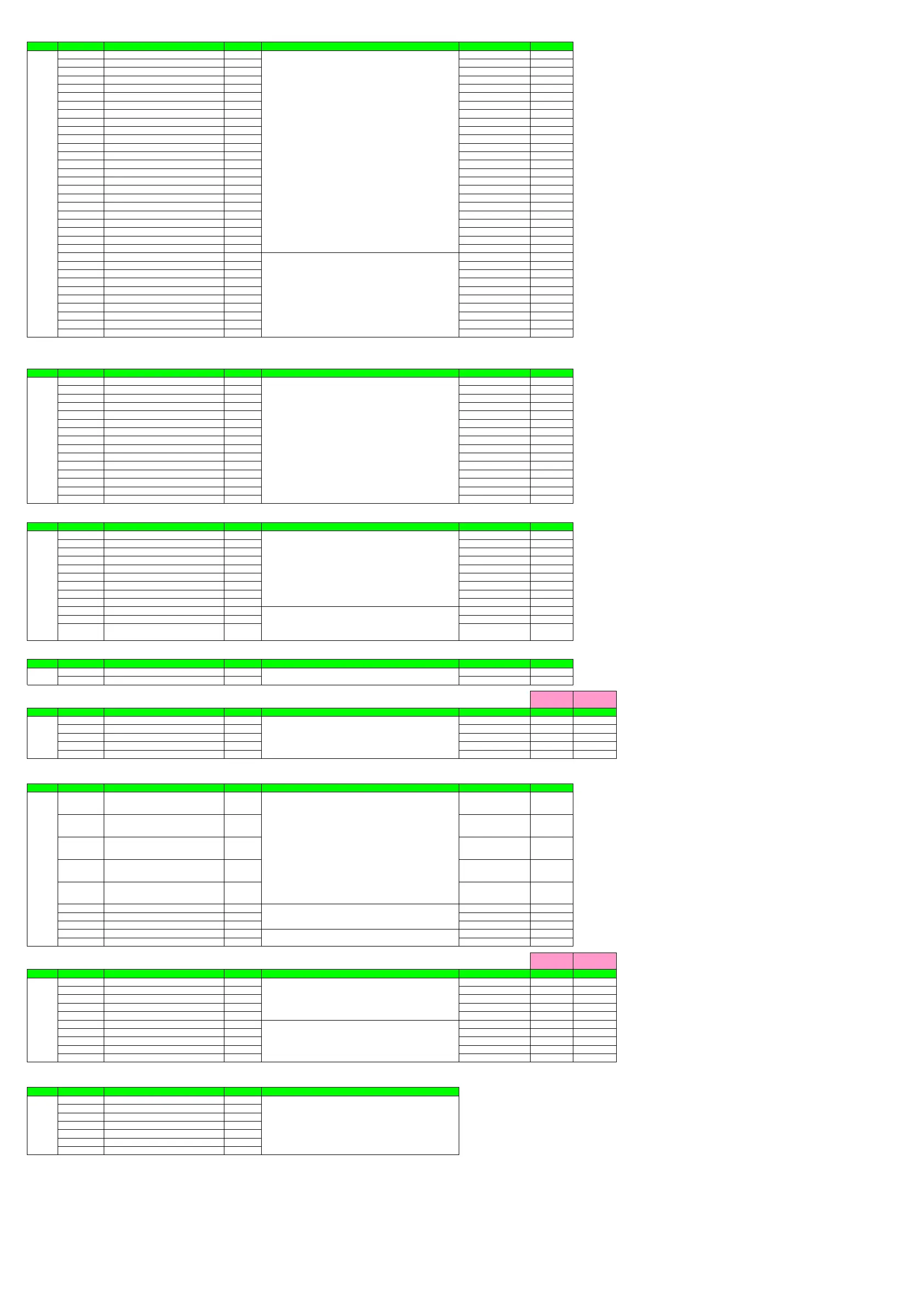
Menu Lock Setting
Menu Symbol Name Display level Setting range Initial value User setting
MLOC CTL [CTL] menu lock PRO OFF
PV [PV] menu lock PRO OFF
MPV [MPV] menu lock PRO OFF
OUT [OUT] menu lock PRO OFF
HBA [HBA] menu lock PRO OFF
R485 [R485] menu lock PRO OFF
ETHR [ETHR] menu lock PRO OFF
PROF [PROF] menu lock PRO OFF
DNET [DNET] menu lock PRO OFF
CC-L [CC-L] menu lock PRO OFF
KEY [KEY] menu lock PRO OFF
DISP [DISP] menu lock PRO OFF
CSEL [CSEL] menu lock PRO OFF
KLOC [KLOC] menu lock PRO OFF
DI.SL [DI.SL] menu lock PRO OFF
DI.NU [DI.NU] menu lock PRO OFF
DI.D [DI.D] menu lock PRO OFF
ALM [ALM] menu lock PRO OFF
DO [DO] menu lock PRO OFF
I/O [I/O] menu lock PRO OFF
SYS [SYS] menu lock PRO OFF
INIT [INIT] menu lock PRO OFF
VER [VER] menu lock PRO OFF
LVL [LVL] menu lock PRO OFF
MODE [MODE] menu lock PRO OFF
CS [CS] menu lock PRO OFF
SP [SP] menu lock PRO OFF
SPS [SPS] menu lock PRO OFF
ALRM [ALRM] menu lock PRO OFF
PVS [PVS] menu lock PRO OFF
PID [PID] menu lock PRO OFF
TUNE [TUNE] menu lock PRO OFF
ZONE [ZONE] menu lock PRO OFF
PPAR [PPAR] menu lock PRO OFF
When each
arameter is dis
la
ed
the terminal area
E1 to E4
is dis
la
ed on Grou
dis
la
.
• Parameter: R485
ETHR
PROF
DNET
CC-L
DI.D
DO
DI Function Registration
Menu Symbol Name Display level Setting range Initial value User setting
DI.SL A/M AUTO/MAN switch STD 5025
R/L REMOTE/LOCAL switch STD OFF
S/R STOP/RUN switch STD 5026
AUTO Switch to AUTO STD OFF
MAN Switch to MAN STD OFF
REM Switch to REMOTE STD OFF
LCL Switch to LOCAL STD OFF
AT Auto-tuning START/STOP switch STD OFF
LAT Latch release STD OFF
LCD LCD backlight ON/OFF switch STD OFF
PVRW PV red/white switch STD OFF
MG1 Message display interruption 1 PRO OFF
MG2 Message display interruption 2 PRO OFF
MG3 Message display interruption 3 PRO OFF
MG4 Message display interruption 4 PRO OFF
DI Function Numbering
Menu Symbol Name Display level Setting range Initial value User setting
DI.NU SP.B0 Bit-0 of SP number EASY OFF
SP.B1 Bit-1 of SP number EASY OFF
SP.B2 Bit-2 of SP number EASY OFF
PN.B0 Bit-0 of PID number STD OFF
PN.B1 Bit-1 of PID number STD OFF
PN.B2 Bit-2 of PID number STD OFF
MP.B0 Bit-0 of manual preset output number STD OFF
MP.B1 Bit-1 of manual preset output number STD OFF
MP.B2 Bit-2 of manual preset output number STD OFF
SP.BC Bit changing method of SP number STD 0
PN.BC Bit changing method of PID number PRO 0
MP.BC
Bit changing method of manual preset output
number
PRO 0
DI1-DI2 Contact Type Setting
Menu Symbol Name Display level Setting range Initial value User setting
DI.D DI1.D DI1 contact type PRO 0
DI2.D DI2 contact type PRO 0
DI Setting
(E1 terminal area)
(DI11-DI15)
(E4 terminal area)
(DI41-DI45)
Menu Symbol Name Display level Setting range Initial value User setting User setting
DI.D DI1.D DIn1 contact type PRO 0
DI2.D DIn2 contact type PRO 0
DI3.D DIn3 contact type PRO 0
DI4.D DIn4 contact type PRO 0
DI5.D DIn5 contact type PRO 0
n: Terminal area number
1 to 4
AL1-AL3 Function Registration
Menu Symbol Name Display level Setting range Initial value User setting
ALM AL1.S AL1 function selection STD 4353
AL2.S AL2 function selection STD 4354
AL3.S AL3 function selection STD 4355
OR.S OUT relay function selection STD OFF
OR2.S OUT2 relay function selection STD OFF
AL1.D AL1 contact type PRO 0
AL2.D AL2 contact type PRO 0
AL3.D AL3 contact type PRO 0
OR.D OUT relay contact type PRO 0
OR2.D OUT2 relay contact type PRO 0
DO Setting
(E1 terminal area)
(DO11-DO15)
(E4 terminal area)
(DO41-DO45)
Menu Symbol Name Display level Setting range Initial value User setting User setting
DO DO1.S DOn1 function selection STD OFF
DO2.S DOn2 function selection STD OFF
DO3.S DOn3 function selection STD OFF
DO4.S DOn4 function selection STD OFF
DO5.S DOn5 function selection STD OFF
DO1.D DOn1 contact type PRO 0
DO2.D DOn2 contact type PRO 0
DO3.D DOn3 contact type PRO 0
DO4.D DOn4 contact type PRO 0
DO5.D DOn5 contact type PRO 0
n: Terminal area number
1 to 4
I/O Display
Menu Symbol Name Display level Setting range
I/O KEY Key status PRO
X000 DI1-DI2 status (equipped as standard) PRO
X100 DI11-DI15 status (E1-terminal area) PRO
X400 DI41-DI45 status (E4-terminal area) PRO
Y000 AL1-AL3 status (equipped as standard) PRO
Y100 DO11-DO12 status (E1-terminal area) PRO
Y400 DO41-DO45 status (E4-terminal area) PRO
0: The assigned function is enabled when the contact input is closed.
1: The assigned function is enabled when the contact input is opened.
Same as AL1.S.
Initial value of E1 and E3 teminal area
All DO settings are OFF.
0: When the event of assigned function occurs, the contact output is closed.
1: When the event of assigned function occurs, the contact output is opened.
0: The assigned function is enabled when the contact input is closed.
1: The assigned function is enabled when the contact input is opened.
Set an I relay number.
Setting range: 4001 to 6000
No function: OFF
Alarm 1: 4353
Alarm 2: 4354
Alarm 3: 4355
Alarm 4: 4357
AUTO (ON ) / MAN (OFF) status: 4193
REM (ON) / LCL (OFF) status: 4194
STOP (ON) / RUN (OFF) status: 4195
FAIL (Normally ON) output: 4256
0: When the event of assigned function occurs, the contact output is closed.
1: When the event of assigned function occurs, the contact output is opened.
0: When the event of assigned function occurs, the contact output is closed.
1: When the event of assigned function occurs, the contact output is opened.
Read only
See User's Manual.
OFF: Display
ON: Nondisplay
Set an I relay number of contact input.
Set “OFF” to disable the function.
Standard terminals
DI1: 5025, DI2: 5026
E1-terminal area
DI11: 5041, DI12: 5042, DI13: 5043, DI14: 5044, DI15: 5045
E4-terminal area
DI41: 5089, DI42: 5090, DI43: 5091, DI44: 5092, DI45: 5093
Set an I relay number of contact input.
Set “OFF” to disable the function.
Standard terminals
DI1: 5025, DI2: 5026
E1-terminal area
DI11: 5041, DI12: 5042, DI13: 5043, DI14: 5044, DI15: 5045
E4-terminal area
DI41: 5089, DI42: 5090, DI43: 5091, DI44: 5092, DI45: 5093
0: Status switch 1
1: Status switch 2
OFF: Display
ON: Nondisplay
Page 17 / 18

 Loading...


