2-17
IM WT310-02EN
Making Preparations for Measurements
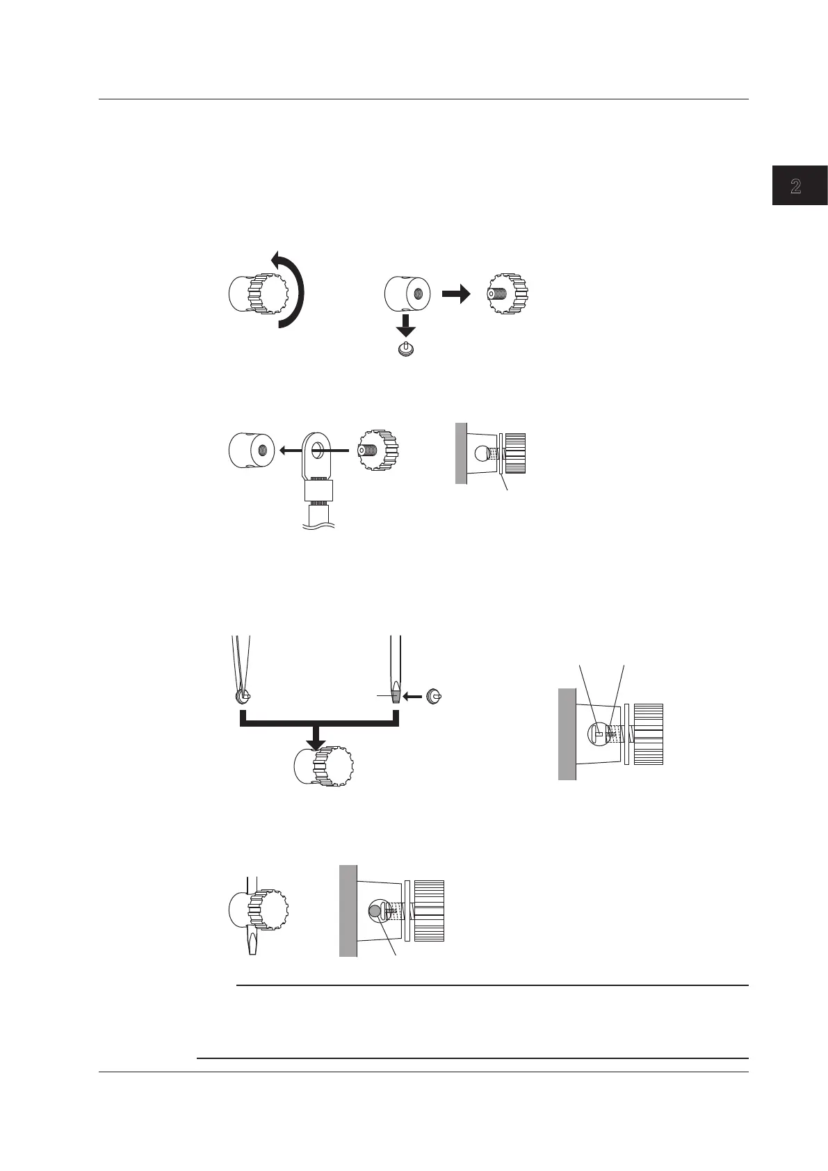
Connecting to a Round Crimped Terminal
To connect a cable with a round crimped terminal to a current input terminal, follow the procedure
below.
1.
Turn the current input terminal knob to loosen it. If the knob becomes difficult to turn, apply
more force to turn it further. Inside the terminal base, the stopper for the knob will disconnect
from the screw portion of the knob, and the knob will become easier to turn.
The stopper for the knob will fall out of the hole in the terminal base. Be careful not to lose the stopper.
Current input terminal
Terminal base Knob
Stopper
2.
Insert the screw of the knob into the crimped terminal, and attach the knob to the terminal base.
Tighten the knob until the tip of the knob screw is slightly visible from the hole in the terminal
base.
3.
Use one of the following methods to insert the stopper into the terminal base and hold it in
place.
• Hold the stopper with tweezers and insert it into the terminal base.
• Wrap adhesive tape around a flathead screwdriver so that the
adhesive side of the tape faces
outward, then attach the stopper to the adhesive tape.
Flathead screwdriverTweezers
Adhesive tape
Stopper shaft
Center hole
4.
Align the shaft of the stopper with the hole in the center of the knob screw. Twist the knob until
the shaft of the stopper enters all the way into the center of the screw.
If the shaft of the stopper doesn’t enter all the way into the screw even after you tighten the knob, insert the
shaft of a screwdriver into the hole in the terminal base, and twist the knob.
Flathead screwdriver shaft
Note
When using a crimped terminal with a measurement cable, be sure to use a crimped terminal that matches
the size of the cable and to crimp the terminal to the cable using the appropriate crimping tool for the
terminal. For precautions about using crimped terminals and crimping tools, see the manuals for the crimped
terminal and the crimping tool that you are using.
2.9 Wiring the Circuit under Measurement for Direct Input