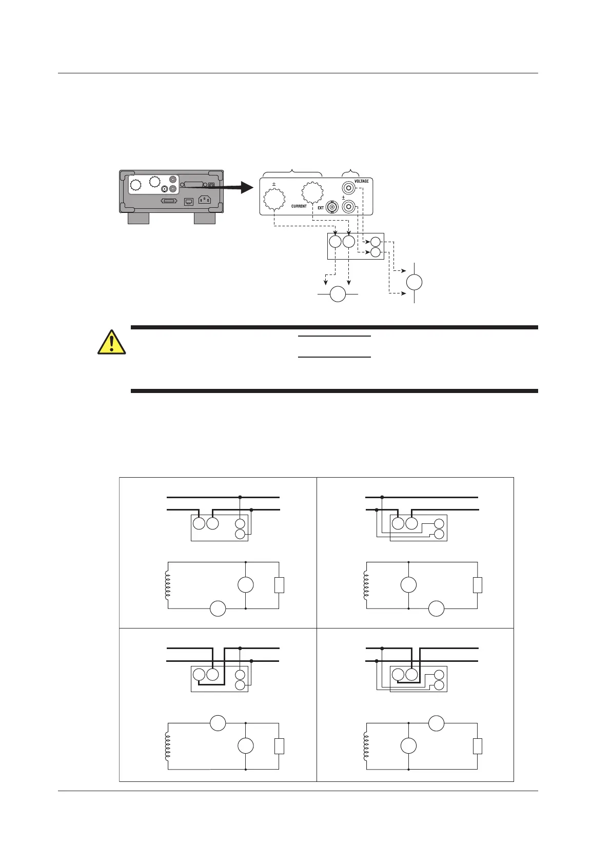
Connecting to the WT310/WT310HC
In the wiring examples that follow, the WT310/WT310HC input elements, voltage input terminals, and
current input terminals are simplified as shown in the following figure.
WT310/WT310HC
I
C
±
Input element
C
±
V
±
U
V
±
The voltage input terminals
and current input terminals
are labeled as U and I,
respectively.
Voltage input
terminals
Current input
terminals
V: VOLTAGE terminal
C: CURRENT terminal
CAUTION
The thick lines on the wiring diagrams are the parts where the current flows. Use wires that are suitable for
the current levels.
Wiring Patterns
When you are wiring a single-phase device, there are the four patterns of terminal wiring positions
shown in the following figures for wiring the voltage input and current input terminals. To select which
pattern to use, see section 2.7.
SOURCE
LOAD
U
I
C
V
LOAD
U
V
I
C
SOURCE
SOURCE
LOAD
SOURCE
LOAD
±
±
±
±
SOURCE
LOAD
SOURCE
LOAD
SOURCE
LOAD
U
I
C
V
SOURCE
LOAD
U
I
C
V
±
±
±
±
C
±
V
±
C
±
V
±
C
±
V
±
C
±
V
±
2.9 Wiring the Circuit under Measurement for Direct Input