2
Strip the insulation of the power cable that you cut, and attach round crimped terminals if
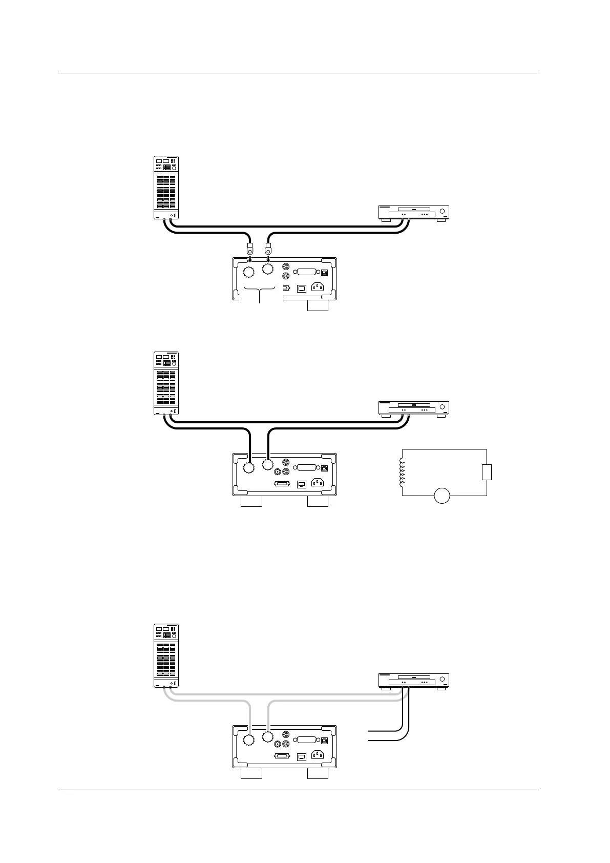
necessary. Connect the power cable to the WT310 in the following ways.
• Power-source-side cable: Connect to the ± current input terminal.
• DUT side cable: Connect to the CURRENT current input terminal.
Pay attention to the terminal polarities so that you don’t attach the cables to terminals (C and ±) with the
wrong polarities.
±
C
Current input terminals
(C: CURRENT terminal)
Round crimped terminal
Power supply
DUT
The wiring for current measurement is complete.
Wiring to the Voltage Input Terminals
Connect the voltage input terminals in parallel with the DUT.
3
Connect the voltage measurement cables to the power supply terminals of the DUT.
Use cables that meet the following conditions.
• Sufficient dielectric strength for the voltage of the circuit under measurement
• Of a size to which the 758931 Safety Terminal Adapter can be attached
• Covering: max. diameter 3.9 mm
• Core wire: max. diameter 1.8 mm
Voltage measurement cables
2.9 Wiring the Circuit under Measurement for Direct Input