2-21
IM WT310-02EN
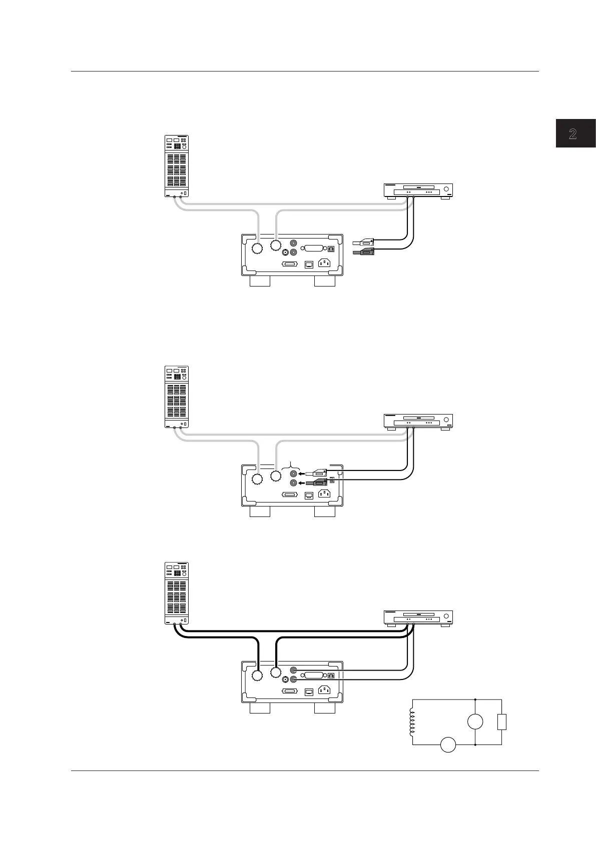
Making Preparations for Measurements
4
Attach 758931 Safety Terminal Adapters to the voltage measurement cables.
For details on how to assemble and attach the safety terminal adapters, see section 2.5.
You can avoid wiring mistakes by connecting a red adapter to the high-voltage cable and a black adapter to
the low-voltage cable.
Safety terminal adapter
Red
Black
5
Connect the safety terminal adapters to the WT310 voltage input terminals.
• Red adapter: Connect to the VOLTAGE voltage input terminal.
• Black adapter: Connect to the ± voltage input terminal.
Pay attention to the terminal polarities so that you don’t attach the cables to terminals (V and ±) with the
wrong polarities.
Voltage input terminals
(V: VOLTAGE terminal)
V
±
The wiring for voltage measurement is complete. The wiring for measuring the power of a single-
phase, two-wire DUT is complete.
SOURCE
LOAD
U
I
C
V
±
±
Power supply
DUT
WT310
2.9 Wiring the Circuit under Measurement for Direct Input