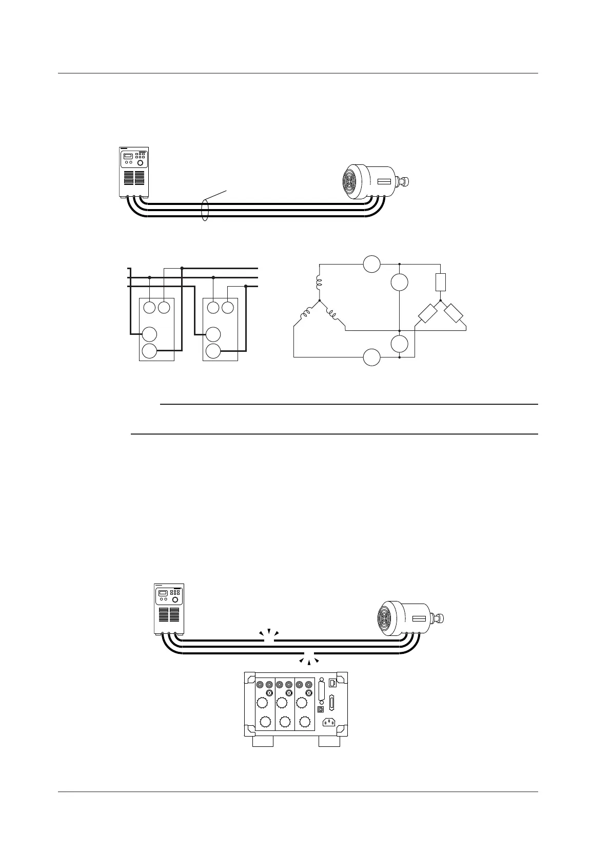
Wiring Procedure Example for a Three-Phase, Three-Wire System
(3P3W)
This example will explain the procedure that you should use to configure the wiring when using the
WT330 to measure the power of a three-phase, three-wire DUT.
TSR
Power supply
DUT
RST
Power cables
This section will explain how to configure the wiring as shown below.
SOURCE
LOAD
I1
±C
±
I3
±
C
U1
±
V
U3
V
R
ST
SOURCE LOAD
Element 1
(V1, A1)
R
S
T
Element 3
(V3, A3)
C
±
±
V
C
±
±
V
Note
The wiring procedure for a single-phase, two-wire DUT on page 2-19 is a useful reference for thinking about
the voltage of each phase and the current wiring.
Order of Connection
Generally, it is easier to follow the wiring diagram if you wire to the current input terminals first and
then to the voltage input terminals. In this example as well, we will wire to the WT330 current input
terminals first and then to the voltage input terminals.
Wiring to the Current Input Terminals
Connect the current input terminals between the R phase and T phase of the power cable.
1
Cut the power cables at the positions where you want to insert the power meter.
2.9 Wiring the Circuit under Measurement for Direct Input