2-27
IM WT310-02EN
Making Preparations for Measurements
2
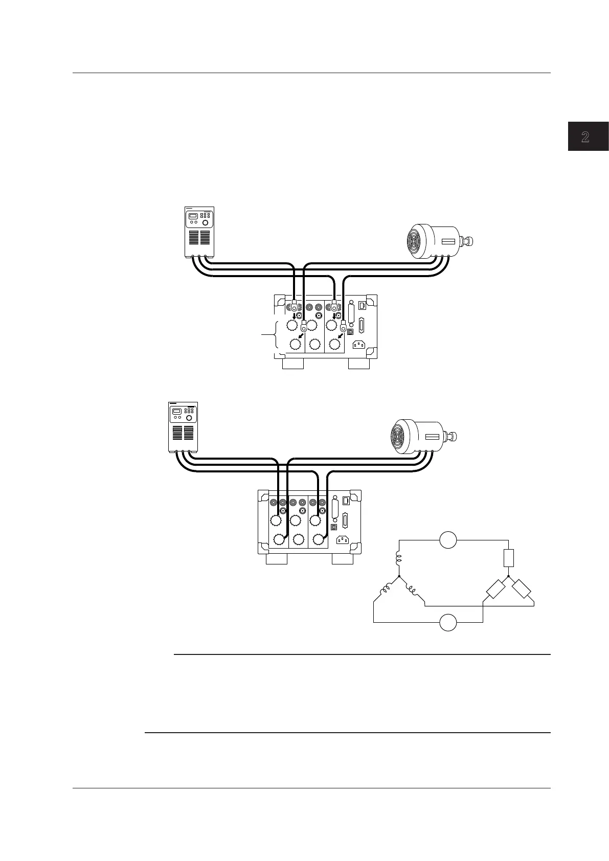
Strip the insulation of the power cables that you cut, and attach round crimped terminals if
necessary. Connect the power cables to the WT330 in the following ways.
• R-phase cable: Connect to element 1.
• Power-source-side cable: Connect to the ± current input terminal of element 1.
• DUT side cable: Connect to the CURRENT current input terminal of element 1.
• T-phase cable: Connect to element 3.
• Power-source-side cable: Connect to the ± current input terminal of element 3.
• DUT side cable: Connect to the CURRENT current input terminal of element 3.
Pay attention to the terminal polarities so that you don’t attach the cables to terminals (C and ±) with the
wrong polarities.
TSR
±
C
Current input terminals
(C: CURRENT terminal)
R
T
1 3
RST
Power supply
DUT
The wiring for current measurement is complete.
TSR
SOURCE
LOAD
I1
±C
I3
±
C
R
ST
1 3
RST
Note
Why You Do Not Have to Connect the WT330 Current Input Terminals to the S-Phase Cable
In a three-phase, three-wire wiring system, there is no neutral line. This means that either the R, S, or T
phase is treated as a virtual neutral line when power is measured. In this example, the S-phase cable is
treated as the virtual neutral line. Therefore, in the voltage terminal connection described later, phase S is
used as the reference to measure the line voltage between phase R and phase S and between phase T and
phase S. This type of power measurement method is referred to as the two-wattmeter method.
2.9 Wiring the Circuit under Measurement for Direct Input