Wiring to the Voltage Input Terminals
Connect the voltage input terminals in parallel with the DUT.
Using phase S as the reference, measure the line voltage between phase R and phase S and
between phase T and phase S.
3
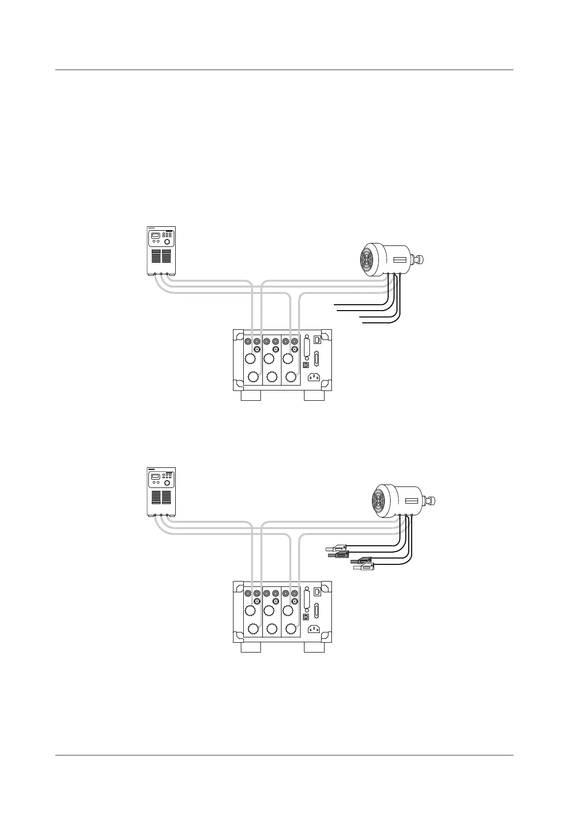
Connect the voltage measurement cables to the power supply terminals of the DUT. Connect
two cables to the S-phase terminal.
Use cables that meet the following conditions.
• Sufficient dielectric strength for the voltage of the circuit under measurement
• Of a size to which the 758931 Safety Terminal Adapter can be attached
• Covering: max. diameter 3.9 mm
• Core wire: max. diameter 1.8 mm
TSR
Voltage measurement
cables
1 3
RST
4
Attach 758931 Safety Terminal Adapters to the voltage measurement cables.
For details on how to assemble and attach the safety terminal adapters, see section 2.5.
You can avoid wiring mistakes by connecting red adapters to the R- and T-phase cables and black adapters
to the S-phase cables.
TSR
Safety terminal adapter
Red
Black
Red
Black
1 3
RST
2.9 Wiring the Circuit under Measurement for Direct Input