2-29
IM WT310-02EN
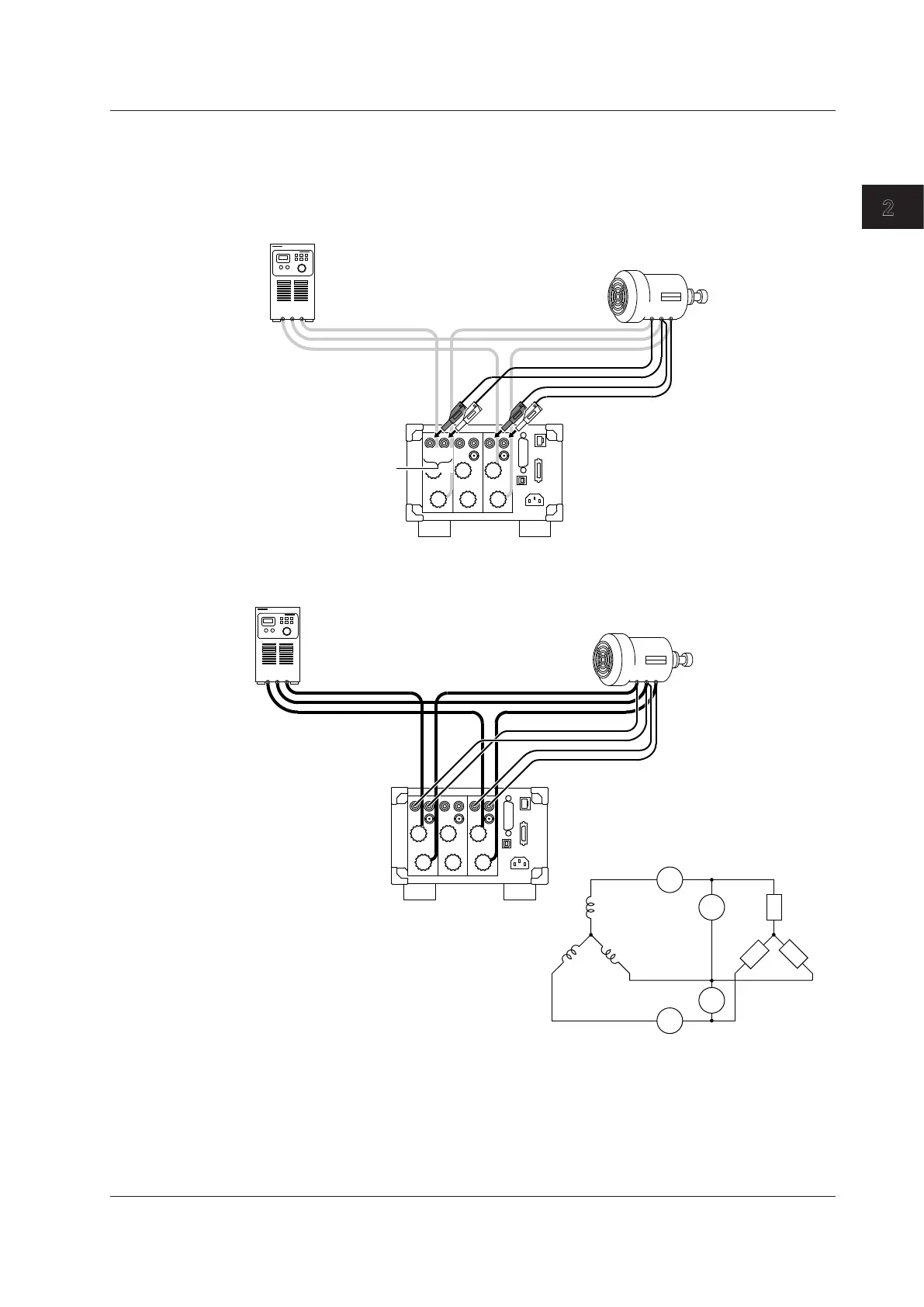
Making Preparations for Measurements
5
Connect the safety terminal adapters to the WT330 voltage input terminals.
• Red R-phase adapter: Connect to the VOLTAGE voltage input terminal of element 1.
• Red T-phase adapter: Connect to the VOLTAGE voltage input terminal of element 3.
• Black S-phase adapters: Connect to the ± voltage input terminals of elements 1 and 3.
Pay attention to the terminal polarities so that you don’t attach the cables to terminals (VOLTAGE and ±)
with the wrong polarities.
TSR
±
V
Voltage input terminals
(V: VOLTAGE terminal)
1 3
RST
R
S
T
S
The wiring for voltage measurement is complete. The wiring for measuring the power of a three-
phase, three-wire DUT is complete.
TSR
SOURCE
LOAD
I1
±C
±
I3
±
C
U1
±
V
U3
V
R
ST
1 3
RST
R
S
T
S
R
T
Power supply
DUT
WT330
2.9 Wiring the Circuit under Measurement for Direct Input