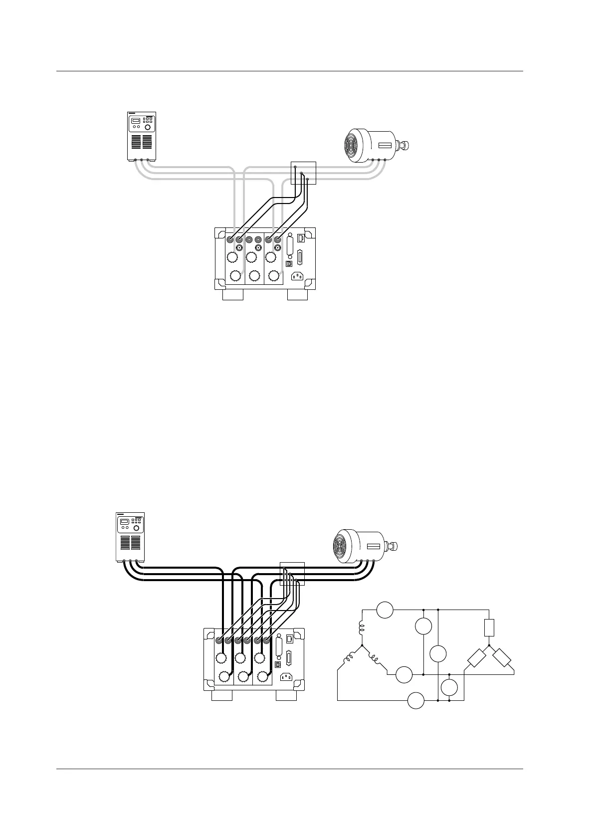
You can also connect to the circuit under measurement by placing a terminal block near the WT330
and connecting the power cables and voltage measurement cables to the terminal block.
Wiring Procedure with the Three-Voltage, Three-Current Method
(3V3A)
You can configure the wiring for the three-voltage, three-current method (3V3A) by adding the following
wiring to the wiring for a three-phase, three-wire system.
Wiring to the Current Input Terminals
In the aforementioned steps 1 and 2, connect the current input terminals of element 2 to the
S-phase power cable.
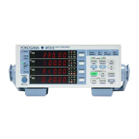
Wiring to the Voltage Input Terminals
In the aforementioned steps 3 to 5, connect the voltage input terminals of element 2 so as to
measure the line voltage between phase R and phase T.
The result of wiring the three-phase, three-wire system shown in the figure above is for the three-
voltage, three-current method (3V3A) is shown below.
TSR
Terminal block
T
S
R
RST
±
V
±
V
±
V
R
S
R
T
T
S
SOURCE
LOAD
I1
±C
±
I3
±
C
U1
±
V
U3
V
R
N
ST
U2
±
V
I2
±C
2.9 Wiring the Circuit under Measurement for Direct Input