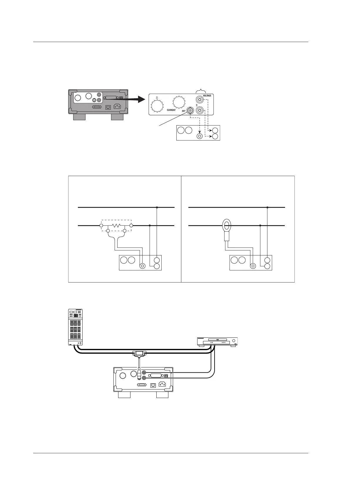
Connecting to the WT310/WT310HC
In the wiring examples that follow, the WT310/WT310HC input elements, voltage input terminals, and
current input terminals are simplified as shown in the following figure.
WT310/WT310HC
Voltage input
terminals
C
±
V
±
External current sensor
input connector
(EXT)
EXT
Wiring Example
The following figures show how to connect to the WT310/WT310HC.
SOURCE
LOAD
Earth side
OUT L OUT H
Shunt-type current sensor
SOURCE
LOAD
Earth side
Clamp-type current sensor
that outputs voltage
C
±
V
±
EXT
C
±
V
±
EXT
When You Are Using a Clamp-type
Current Sensor That Outputs Voltage
When You Are Using a Shunt-Type
Current Sensor
When you use a shunt-type current sensor in the wiring configuration shown at the bottom of page
2-21, the configuration changes as shown in the figure below.
Shunt-type current sensor
B9284LK
2.10 Wiring the Circuit under Measurement When Using Current Sensors