2-35
IM WT310-02EN
Making Preparations for Measurements
Connecting to the WT330
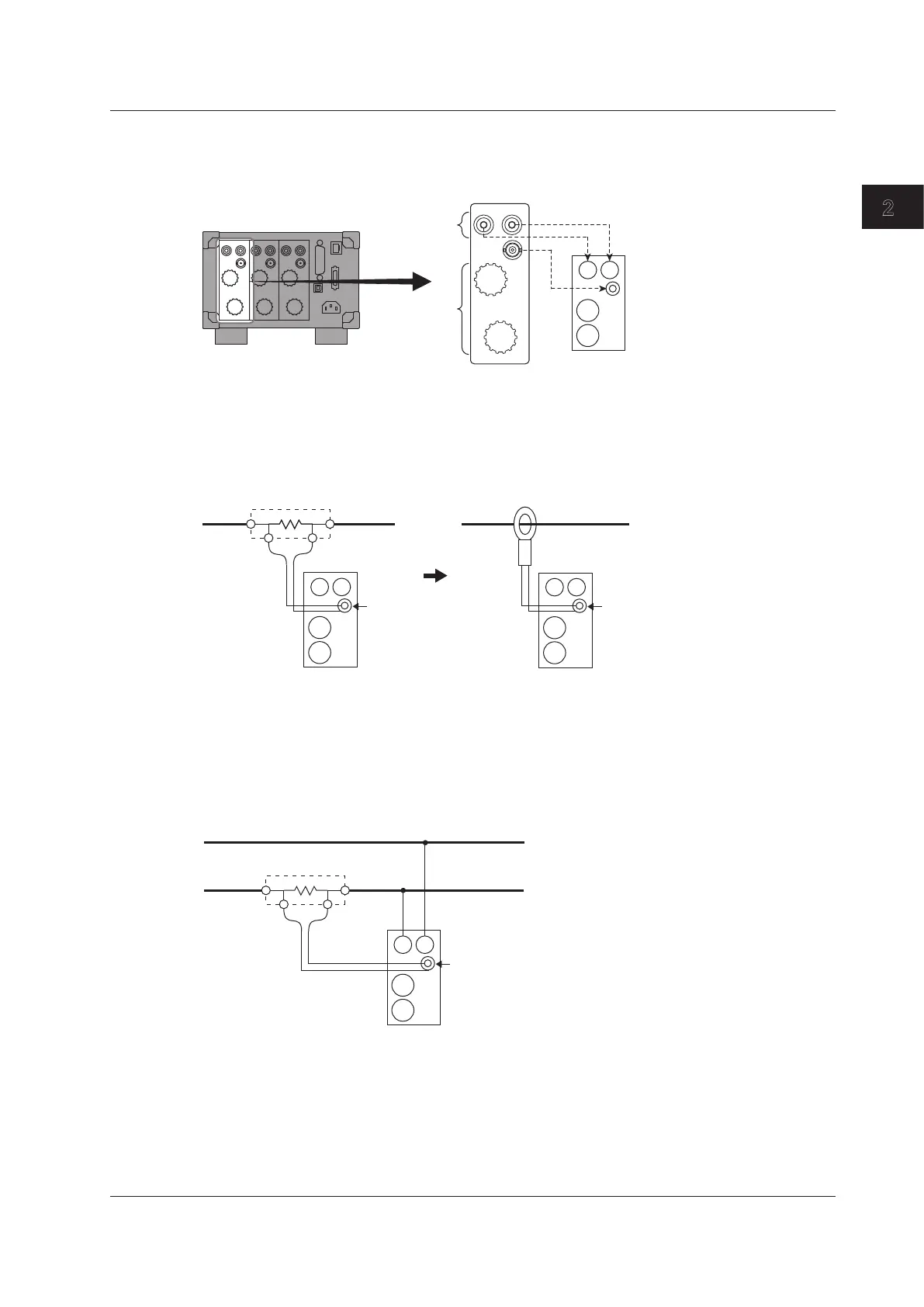
In the wiring examples that follow, the WT330 input elements, voltage input terminals, and current
input terminals are simplified as shown in the following figure.
VOLTAGE
±
±
CURRENT
EXT
EXT
C
±
±
V
Input element
Voltage input
terminals
Current input
terminals
WT330
Also, the wiring example is for when a shunt-type current sensor is connected. When connecting
a clamp-type current sensor that outputs voltage, substitute the shunt-type current sensor with the
clamp-type current sensor.
Shunt-type current sensor
±
I
OUT LOUT H
Input element
Input element
Clamp-type current sensor
that outputs voltage
EXT
C
±
±
V
EXT
C
±
±
V
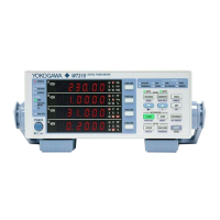
Wiring Example of a Single-Phase, Two-Wire System (1P2W) with
a Shunt-Type Current Sensor
The following wiring example shows how to configure the wiring to connect to input element 1. To
configure the wiring for other input elements, substitute the numbers in the figures with the appropriate
element numbers.
SOURCE
LOAD
Earth side
OUT L OUT H
Element 1
EXT
C
±
±
V
Shunt-type current sensor
2.10 Wiring the Circuit under Measurement When Using Current Sensors