S
Sergey KopylovOct 19, 2025
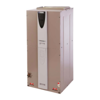
Good morning. Please help me. For me need order new Evaporator Air handling unit MAKH 1409 R. I can't found type for this Evaporator. Photo Attach.
Good morning. Please help me. For me need order new Evaporator Air handling unit MAKH 1409 R. I can't found type for this Evaporator. Photo Attach.
Provides an overview of the YORK air handling unit (AHU) design and standards.
Explains the manual's content, reproduction rights, and user guidelines for safe operation.
Details the warranty terms, conditions, and requirements for YORK AHUs.
Outlines user and technician responsibilities for safe operation and maintenance.
General inspection steps and prerequisites before starting the AHU.
Instructions for inspecting fan assembly components, condition, and alignment.
Guidance on checking belt alignment, tension, and sheave condition for optimal performance.
Procedures for checking and adjusting fan base isolators for proper operation.
Crucial warnings and step-by-step procedures before operating the AHU.
Steps to verify fan motor operation, voltage, phase, and rotation.
Instructions for checking damper position, linkage, and actuators.
Procedure for releasing and setting the counterbalance for back draft dampers.
Explains different damper configurations and their functions for airflow control.
Details on connecting air measuring devices and calculating airflow rates.
Outlines available damper configurations (25%, 25%/75%, 100%) for airflow measurement.
Details on optional end devices and jumper selections for AMS-60 stations.
Guidelines for setting up VFDs to prevent operation at resonant frequencies.
Configuration and start-up procedures for Airxchange®, Innergy tech®, and Thermotech® wheels.
Safety warnings and general instructions for starting indirect fired gas heating systems.
Safety warnings, application information, and procedures for starting electric heaters.
General operational warnings, test and balance procedures, and component limits.
Guidelines for checking motor amperage, belts, and sheaves for proper function.
Outlines general maintenance requirements according to ASHRAE standards.
General inspection of cabinet, doors, panels, hoods, louvers, and bird screens.
Procedures for removing, cleaning, and checking the fan segment components.
Standard procedures for operating and adjusting the motor base for belt alignment.
Steps to check and adjust belt tension using a tension gauge.
Importance of sheave alignment for belt and bearing life and methods for alignment.
Verifying bearing types and guidelines for lubricating fan bearings and motors.
Contractor responsibilities for installing and maintaining UV lamps.
Guidelines for checking, cleaning, and replacing filter segments.
Procedures for cleaning economizer dampers and performing hardware checks.
Lists tools and materials for cleaning coil segments and procedures.
Tools, materials, and schedule for cleaning condensate drain pans, traps, and lines.
Measures to protect coils from freezing damage during cold weather operations.
Information on energy recovery wheel vendors and procedures for cleaning and adjusting seals.
Basic maintenance instructions for the ECONO-DISK® and P-CONE® systems.
Lists essential tools and equipment required for servicing AHUs.
General service information, tags, decals, and provided documentation.
Overview of common HVAC air system issues and related components.
Description and use of inclined, filter, U-tube, and slack tube manometers.
Explanation of duct pressures, including velocity, static, and total pressure relationships.
Information required when contacting Johnson Controls for technical assistance.
Procedures for adjusting, removing, and installing fixed pitch sheaves.
Instructions for installing JVS and FHP adjustable pitch sheaves.
Wiring diagram for a standard full voltage motor starter.
Wiring diagram for a full voltage starter with a single point power connection.
Instructions for installing an outside air damper kit relay.
Shows an example of a Solution XT termination chart inside the enclosure door.
Wiring diagram for typical Factory Packaged Controls (FPC) systems.
Wiring detail for a transformer enclosure, shown with the cover open.
Diagram illustrating the wiring for a transformer unit.
Wiring diagrams for UV control panels, covering 8 amps and greater than 8 amps.
Wiring diagrams for gas heat units with single and three-phase transformers.
Typical wiring diagrams for electric heat control systems.
Checklist for AHU start-up procedures, unit inspection, and safety requirements.
General unit inspection and safety procedures before AHU start-up.
Checks for fan bearings, sheaves, alignment, and fan base isolators.
Step-by-step sequence for performing the AHU start-up procedure.
Required documentation for complying with long-term storage requirements.
General procedures for preparing units for long-term storage, including inspections.
Storage requirements for electrical components to prevent corrosion and damage.
Procedures for protecting mechanical components like shafts and sheaves during storage.
Procedures for monthly inspections of motors, drives, and refrigerant coils during storage.
Quarterly checks for unit assembly and annual tasks for electrical and mechanical components.
| Cooling Capacity | Varies by model |
|---|---|
| Heating Capacity | Varies by model |
| Airflow Range | Varies by model |
| Static Pressure | Varies by model |
| Power Supply | Varies by model |
| Sound Pressure Level | Varies by model |
| Filter Class | Varies by model |
| Insulation | Fiberglass |