5120416-XIM-C-0216
36 Johnson Controls Unitary Products
Air Balance
Start the supply air blower motor. Adjust the resistances in both
the supply and the return air duct systems to balance the air
distribution throughout the conditioned space. The job
specifications may require that this balancing be done by
someone other than the equipment installer.
To check the supply air CFM after the initial balancing has been
completed:
1. Remove the two 5/16” dot plugs from the blower motor and
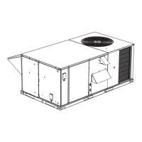
the filter access panels shown in the Unit Dimensions and
Rear View Clearances Figure 6.
2. Insert at least 8" of 1/4 inch tubing into each of these holes
for sufficient penetration into the air flow on both sides of
the indoor coil.
NOTE: The tubes must be inserted and held in a position
perpendicular to the air flow so that velocity pressure
will not affect the static pressure readings.
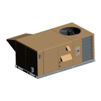
3. Using an inclined manometer, determine the pressure drop
across a dry evaporator coil. Since the moisture on an
evaporator coil may vary greatly, measuring the pressure
drop across a wet coil under field conditions would be
inaccurate. To assure a dry coil, the compressors should
be deactivated while the test is being run.
Figure 22: Pressure Drop Across A Dry Indoor Coil Vs.
Supply Air CFM For All Unit Tonnages
4. Knowing the pressure drop across a dry coil, the actual
CFM through the unit can be determined from the curve in
Pressure Drop vs. Supply Air CFM Figure 22.
After readings have been obtained, remove the tubes and reinstall the two 5/16” dot plugs that were removed in Step 1.
Table 14: Blower Motor And Drive Data
MODEL
SIZE
DRIVE
1
1. All 50 Hz DM180-300 models come standard with factory filtered High Static Drive.
BLOWER
RANGE
(RPM)
MOTOR
2
2. All motors have a nominal speed of 1450 RPM, a 1.15 service factor and a solid base. They can operate to the limit of their service factor because
they are located in the moving air, upstream of any heating device.
ADJUSTABLE MOTOR PULLEY
3
3. Do NOT close this pulley below 1 turn open.
FIXED BLOWER PULLEY
BELT
(NOTCHED)
kW/HP FRAME
EFF.
(%)
DESIG-
NATION
PITCH
DIA.
(mm/IN.)
BORE
(mm/IN.)
DESIG-
NATION
PITCH
DIA.
(mm/IN.)
BORE
(mm/IN.)
DESIG-
NATION
PITCH
LENGTH
(mm/IN.)
QTY.
180
High
Static
1030/1240 3.7/5.0 184 T 83 1VP62
109-135
4.3-5.3
29/1-1/8 BK75 175/6.9 25/1 BX68 1773/69.8 1
240
High
Static
895-1080 5.6/7.5 213 T 87 1VP75
140-165
5.5-6.5
35/1-3/8 BK100 239/9.4
30/1-3/16
4
4. Requires bushing (included in kit).
BX81 2103/82.8 1
300
High
Static
950/1130 7.5/10 254 T 89
1LVP58
B70A
157-188
(6.2-7.4)
A2
Bushing
1B5V94 241 (9.5)
B
Bushing
5VX840 2134/84 1
Table 15: Power Exhaust Performance
MOTOR
SPEED
STATIC RESISTANCE OF RETURN DUCTWORK, IWG
0.2 0.3 0.4 0.5 0.6
CFM KW CFM KW CFM KW CFM KW CFM KW
HIGH* 5250 0.83 4500 0.85 4200 0.88 3750 0.93 3000 0.99
MEDIUM 4900 0.77 3900 0.79 3500 0.82 2900 0.85 - -
LOW 4400 0.72 3700 0.74 3000 0.78 - - - -
Failure to properly adjust the total system air quantity
can result in extensive blower damage.
0.25
0.3
0.35
0.4
0.45
0.5
0.55
0.6
0.65
45678910111213
NOMINAL CFM (THOUSANDS) SUPPLY AIR
PRESSURE DROP (IWG)
240 MBH