3-8
SM-18001-rev.1
TROUBLESHOOTING
1 2 3 4 5 6
ON
OFF
1 2 3 4 5 6
ON
OFF
DSW6 (Tens Digit)
RSW1 (Units Digit)
Setting
Position
Set by inserting
slotted screwdriver
into the groove.
Ex.) Set at No.16 Unit
DSW6
RSW1
Set No.1 Pin at ON side
Set at "6"
3
4
1
0
8
9
2
5
6
7
3
4
1
0
8
9
2
5
6
7
Factory settings for DSW6 and RSW1 are set at "0".
For the units supporting H-LINK II, the unit numbers can
be set for a maximum of 64 indoor units (No.0 to 63).
(4) Unit No. Setting (RSW1 and DSW6)
The indoor unit numbers of all indoor units
are not required. The indoor unit numbers
are set by the auto-address function. If the
indoor unit number setting is required, set the
unit numbers of all indoor units respectively
and serially by following setting positions. It
is recommended to assign a number to each
indoor unit beginning with “1.” Though a
maximum of 64 indoor units per refrigerant
system can be connected to the H-LINK ll
System, available numbers range from 0 to 63.
Therefore, the applicable number for the 64th
indoor unit is “0.”
For centralized control, this setting is required.
(5) Capacity Code Setting (DSW3)
No setting is required because of the factory setting. This switch is utilized for setting the capacity
code which corresponds to the capacity of the indoor unit.
Setting Position
18
Indoor Unit Capacity
(MBH)
24 30 36 48
1 2 3 4
ON
OFF
1 2 3 4
ON
OFF
1 2 3 4
ON
OFF
1 2 3 4
ON
OFF
1 2 3 4
ON
OFF
Setting Position
0806 12
Indoor Unit Capacity
(MBH)
Indoor Unit Capacity
(MBH)
15 18
Setting Position
24 30 36 48
1 2 3 4 5 6
ON
OFF
1 2 3 4 5 6
ON
OFF
1 2 3 4 5 6
ON
OFF
1 2 3 4 5 6
ON
OFF
1 2 3 4 5 6
ON
OFF
1 2
3 4 5 6
ON
OFF
1 2 3 4 5 6
ON
OFF
1 2 3 4 5 6
ON
OFF
1 2 3 4 5 6
ON
OFF
0806 12
Indoor Unit Capacity
(MBH)
15 18
Setting Position
1 2 3 4 5 6
ON
OFF
1 2 3 4 5 6
ON
OFF
1 2 3 4 5 6
ON
OFF
1 2 3 4 5 6
ON
OFF
1 2 3 4 5 6
ON
OFF
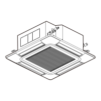
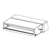
● Ducted High Static
● Ducted Medium Static
● Ducted Slim
 Loading...