25
Emergency Heat (W) - The blower will be started on “W” speed,
10 seconds later the first stage of electric heat will be turned on.
If the emergency heat demand is not satisfied after 2 minutes the
second electric heat stage will be energized.
Blower (G) - The blower will start immediately upon receiving a
thermostat G command. If there are no other commands from the
thermostat the ECM will run on “G” speed until the G command is
removed. Regardless of blower input (G) from the thermostat, the
blower will remain on for 30 seconds at the end of each heating
cycle.
Cooling Operation
In all cooling operations, the reversing valve directly tracks the O
input. Thus, anytime the O input is present, the reversing valve will
be energized.
Cooling, 1st Stage (Y1, O) - The blower is started on “Y1” speed
immediately and the compressor is energized 10 seconds after the Y1
input is received.
Cooling, 2nd Stage (Y1, Y2, O) - The compressor will be staged
to full capacity 20 seconds after Y2 input is received. The 5 speed
ECM blower will shift to Y2 speed immediately.
Emergency Shutdown - Four (4) seconds after a valid ES input,
P2-7 is present, all control outputs will be turned off and remain
off until the emergency shutdown input is no longer present. The
first time that the compressor is started after the control exits the
emergency shutdown mode, there will be an anti-short cycle delay
followed by a random start delay. Input must be tied to common to
activate.
Continuous Blower Operation - The blower output will be
energized any time the control has a G input present, unless the
control has an emergency shutdown input present. The blower
output will be turned off when G input is removed.
Load Shed - The LS input disables all outputs with the exception
of the blower output. When the LS input has been cleared, the anti-
short cycle timer and random start timer will be initiated. Input must
be tied to common to activate.
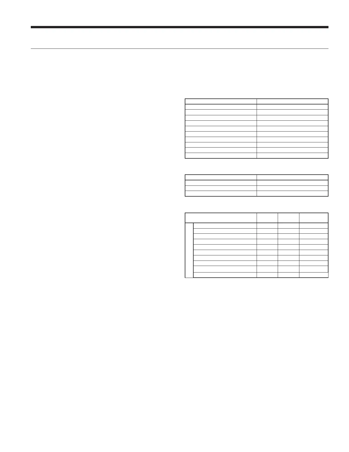
Aurora ‘Base’ Control LED Displays
These three LEDs display the status, configuration, and fault
codes for the control. These can also be read in plain English via
the Aurora AID Tool.
Status LED (LED3, Green)
Description of Operation Fault LED, Green
Normal Mode ON
Control is Non-functional OFF
Test Mode Slow Flash
Lockout Active Fast Flash
Dehumidification Mode Flash Code 2
(Future Use) Flash Code 3
(Future Use) Flash Code 4
Load Shed Flash Code 5
Emergency Shutdown Flash Code 6
Smart Grid Flash Code 7
Configuration LED (LED2, Yellow)
Description of Operation Configuration LED, Yellow
No Software Overwritten Flashing ECM Setting
DIP Switch was Overwritten Slow Flash
ECM Configuration Mode Fast Flash
Fault LED (LED1, Red)
Red Fault LED
LED Flash
Code*
Lockout Reset/Remove
ABC Basic Faults
Normal - No Faults OFF –
Fault - Input 1 No Auto
Fault - High Pressure 2 Yes Hard or Soft
Fault - Low Pressure 3 Yes Hard or Soft
Fault - Freeze Detection FP2 4 Yes Hard or Soft
Fault - Freeze Detection FP1 5 Yes Hard or Soft
Fault - Condensate Overflow 7 Yes Hard or Soft
Fault - Over/Under Voltage 8 No Auto
Fault - FP1 Sensor Error 11 Yes Hard or Soft
Fault - CritComErr 19 NO Auto
NOTE: All codes >11 use long flash for tens digit and short flash for the ones digit. 20,
30, 40, 50, etc. are skipped.
The Aurora ‘Base’ Control System cont.
LX SERIES INSTALLATION MANUAL
 Loading...