45
Troubleshooting cont.
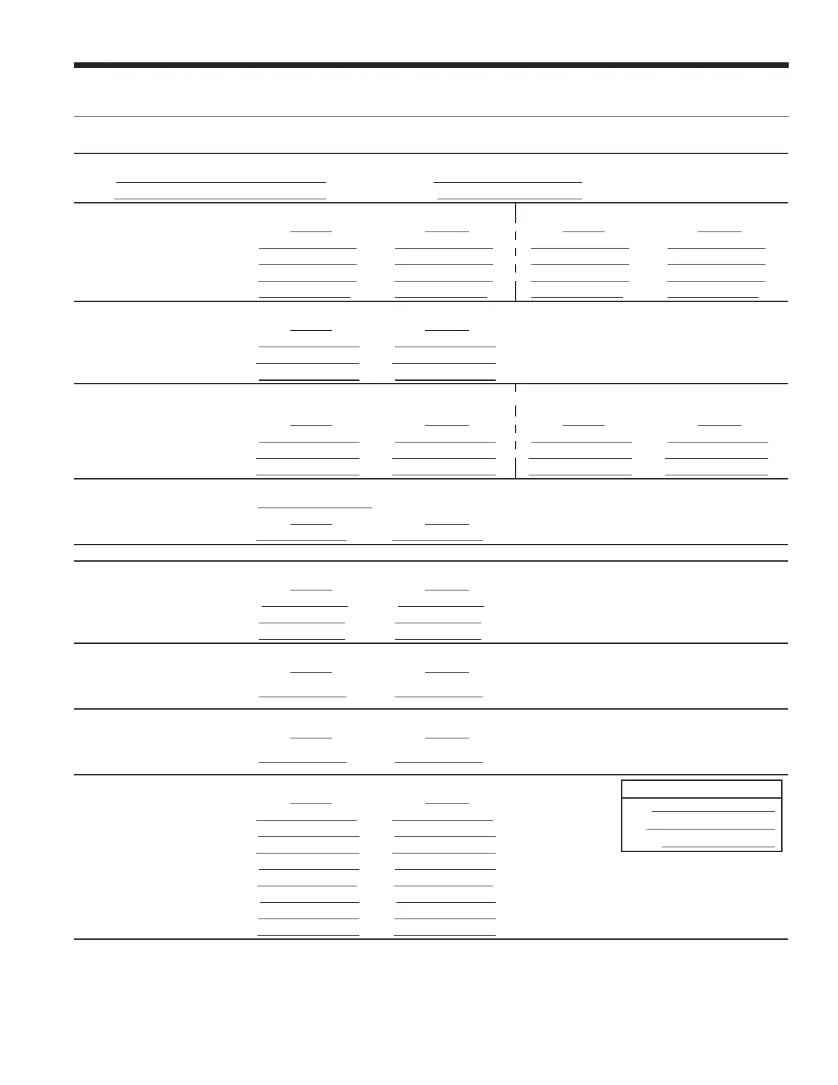
Single Speed/Dual Capacity Startup/Troubleshooting Form
1. Job Information
Model # Job Name: Loop: Open / Closed
Serial # Install Date: Hot Water Generator: Y / N
2. Flow Rate in gpm SOURCE COAX LOAD COAX (Water-to-Water)
HEATING COOLING HEATING COOLING
WATER IN Pressure:
a. psi a. psi a. psi a. psi
WATER OUT Pressure:
b. psi b. psi b. psi b. psi
Pressure Drop: a - b
c. psi c. psi c. psi c. psi
Look up flow rate in table:
d. gpm d. gpm d. gpm d. gpm
3. Temp. Rise/Drop Across Air Coil
1
HEATING COOLING
SUPPLY AIR Temperature:
e. °F e. °F
RETURN AIR Temperature:
f. °F f. °F
Temperature Difference:
g. °F g. °F
4. Temp. Rise/Drop Across Coaxial
Heat Exchanger
SOURCE COAX LOAD COAX (Water-to-Water)
HEATING COOLING HEATING COOLING
WATER IN Temperature:
h. °F h. °F h. °F h. °F
WATER OUT Temperature:
i. °F i. °F i. °F i. °F
Temperature Difference:
j. °F j. °F j. °F j. °F
5. Heat of Rejection (HR)/Heat of Extraction (HE)
Brine Factor
2
: k.
HEATING COOLING
HR/HE = d x j x k
l. Btu/h l. Btu/h
STEPS 6-9 NEED ONLY BE COMPLETED IF A PROBLEM IS SUSPECTED.
6. Watts ENERGY MONITOR
HEATING COOLING
Volts:
m. Volts m. Volts
Total Amps (Comp. + Blower)
3
: n. Amps n. Amps
Watts = m x n x 0.85:
o. Watts o. Watts
7. Capacity
HEATING COOLING
Cooling Capacity = l - (o x 3.413):
p. Btu/h p. Btu/h
Heating Capacity = l + (o x 3.413):
8. Efficiency
HEATING COOLING
Cooling EER = p / o:
q. Btu/h q. Btu/h
Heating COP = p / (o x 3.413):
9. Superheat (S.H.)/Subcooling (S.C.)
Software Version
ABC:
IZ2:
T’STAT:
HEATING COOLING
Suction Pressure:
r. psi r. psi
Suction Saturation Temperature:
s. °F s. °F
Suction Line Temperature:
t. °F t. °F
S.H. = t - s
u. °F u. °F
Head Pressure:
v. psi v. psi
High Pressure Saturation Temp:
w. °F w. °F
Liquid Line Temperature
4
: x. °F x. °F
S.C. = w - x
y. °F y. °F
NOTES:
1
Steps 3-9 should be conducted with the hot water generator disconnected.
2
Use 500 for pure water, 485 for methanol or Environol™. (This constant is derived by multiplying the weight of one gallon of water (8.34) times the minutes
in one hour (60) times the specific heat of the fluid. Water has a specific heat of 1.0.
3
If there is only one source of power for the compressor and blower, amp draw can be measured at the source wiring connection.
4
Liquid line is between the coax and the expansion device in the cooling mode; between the air coil and the expansion device in the heating mode.
LX SERIES INSTALLATION MANUAL
 Loading...