YORK INTERNATIONAL
FORM 160.73-O2 (605)
10
2. To start the chiller, press the COM PRES SOR
START switch. This switch will au to mat i cal ly
spring return to the RUN position. (If the unit was
pre vi ous ly started, press the STOP/RE SET side
of the COMPRESSOR switch and then press the
START side of the switch to start the chiller.) When
the start switch is energized, the Control Center is
placed in an operating mode and any malfunction
will be not ed by messages on a graphic display.
Any malfunctions which oc cur dur ing
STOP/RE SET are also displayed.
When the chiller is shut down, the prerotation vanes will
close au to mat i cal ly to prevent load ing the com pres sor
on start-up.
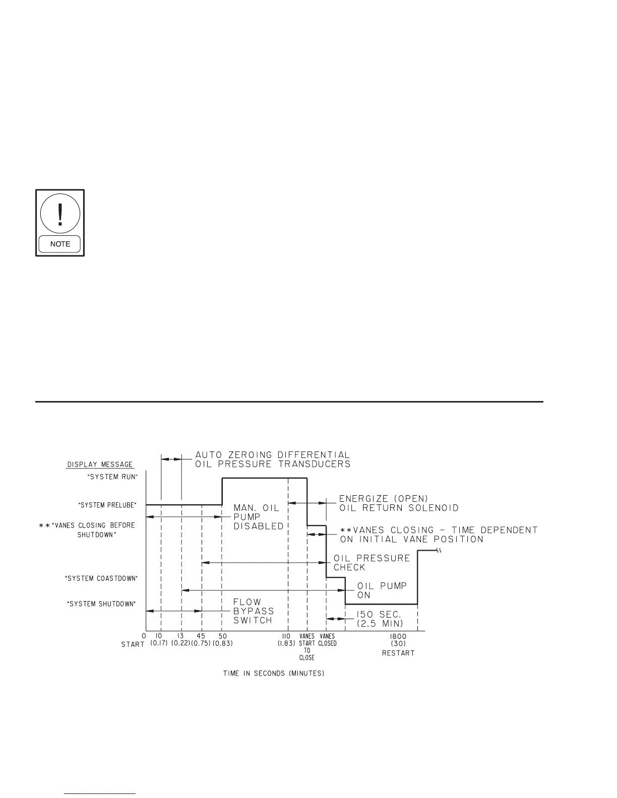
When the chiller starts to op er ate, the fol low ing au-
to mat ic sequences are initiated: (Refer to Fig. 4 & 5,
“Chill er Start ing & Shutdown Se quence Chart”.)
1. The OptiView Control Center display mes sage will
read SYSTEM PRELUBE for the fi rst 50 sec onds
of the start ing sequence.
2. The oil pump will start to circulate oil for a 50 sec ond
pre-run to establish oil fl ow and ad e quate lu bri ca tion
to all bearings, gears, and rotating sur fac es within
the compressor.
The high and low oil pressure transducers (OP) and
the oil temperature sensor (RT3) will sense any mal-
function in the lubrication system.
3. The anti-recycle timer (non-VSD Chillers only)
software function will op er ate af ter the 50 seconds
of pre-run time. At this time, the timer will be initi-
ated and will run for 30 min utes after the compressor
starts. If the chiller shuts down during this period of
time, it cannot be started until the timer com pletes
the 30 minute cy cle.
4. The chilled liquid pump contacts will close, start-
ing the chilled liquid pump, to allow liquid fl ow
through the evaporator when the COMPRESSOR
start switch is energized.
5. After the fi rst 50 seconds of operation, the com-
pres sor will start.
6. For display messages and information per tain ing to
the op er a tion of the OptiView™ Con trol Cen ter, re fer
to Form 160.54-O1.
FIG. 4 – CHILLER STARTING SEQUENCE & SHUT DOWN SEQUENCE
(EM STARTER & SOLID STATE STARTER)
LD04040
** NOT FOR ALL SHUTDOWNS. REFER TO “DISPLAY MES-
SAG ES” SECTION OF THIS MANUAL.