FORM 160.73-O2 (605)
9
YORK INTERNATIONAL
CHECKING THE OIL LEVEL
IN THE OIL RESERVOIR
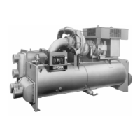
Proper operating oil level – During operation, the oil
level should fall to the “Operating Range” identifi ed on
the vertical oil level indicator label. See Figure 3.
• If the oil level during operation is in the “Over
Full” region of the oil level indicator, oil should be
removed from the oil reservoir, This reduces the oil
level to the “Operating Range”.
• If the oil level during operation is in
the “Low Oil” region of the oil level
indicator, oil should be added to the
oil reservoir. (See “Oil Charging Pro-
cedure”, page 22)
START-UP PROCEDURE
Pre-Starting
Prior to starting the chiller, observe the OptiView
Control Center. Make sure the display reads SYSTEM
READY TO START.
To pre-start the chiller, use the following procedure:
1. Oil Heater – The oil heater must be energized for
12 hours prior to starting the chiller.
2. Prior to start, the clock must be programmed for the
proper day and time. Any setpoints which are de sired
to be changed may be programmed. All Control Cen-
ter setpoints should be pro grammed before the chiller
is started. (Refer to Form 160.54-O1).
Vent any air from the chiller water
boxes prior to starting the water
pumps. Failure to do so will result in
pass baffl e damage.
START-UP
1. If the chilled water pump is manually operated, start
the pump. The Control Center will not allow the
chill er to start unless chilled liquid fl ow is es tab lished
through the unit. (A fi eld supplied chilled wa ter fl ow
switch is required.) If the chilled liquid pump is wired
to the Microcomputer Control Cen ter the pump will
au to mat i cal ly start, therefore, this step is not neces-
sary.
System Op er at ing Pro ce dures
SECTION 2
SYSTEM OPERATING PROCEDURES
OIL HEATERS
If the oil heater is de-energized during a shut down pe ri od,
it must be energized for 12 hours prior to start ing com-
pres sor, or remove all oil and re charge com pres sor with
new oil. (See “Oil Charging Pro ce dure”, page 22.)
OIL HEATER OPERATION
The oil heater operation is controlled by the OptiView™
Control Center. The heater is turned on and off to main-
tain the oil temperature differential to a val ue 50°F
(27.8°C) above the condenser saturation tem per a ture.
This is the target value and if the oil tem per a ture falls to
4°F (2.2°C) or more below the target, the heater is turned
on. It is turned off when the oil temperature increases to
3°F (1.7°C) above the target value.
If the target value is greater than 160°F (71°C), the tar get
de faults to 160°F (71°C). If the target value is less than
110°F (43.3°C), it defaults to 110°F (43.3°C).
To prevent over heat ing of the oil in the event of a con-
trol center component fail ure, the oil heat er ther mo stat
(1HTR) is set to open at 180°F (82°C).
FIG. 3 – OIL LEVEL INDICATOR
LD08647
Comply with EPA and Local reg u -
la tions when re mov ing or disposing
of Re frig er a tion System oil!