FORM 160.73-O2 (605)
11
YORK INTERNATIONAL
2
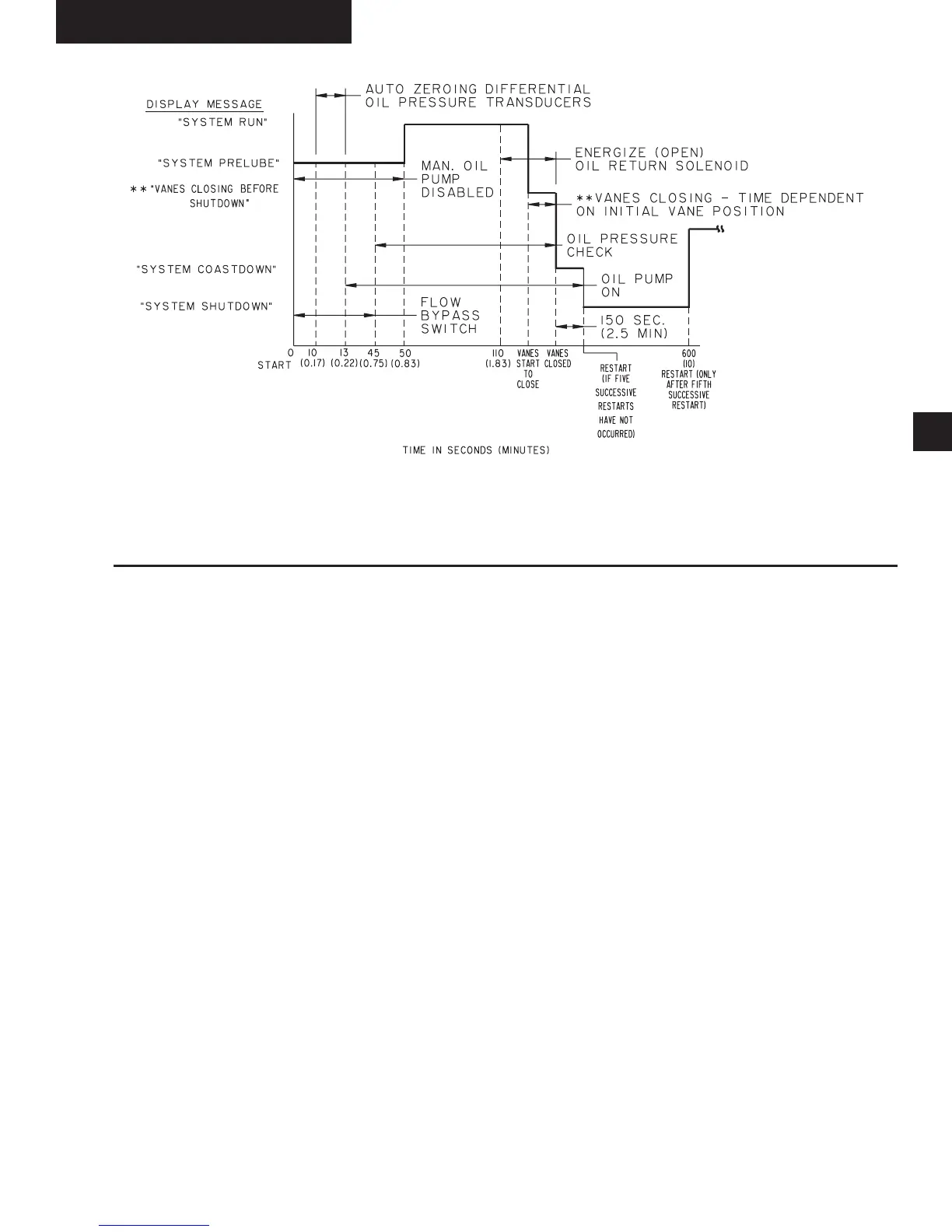
FIG. 5 – CHILLER STARTING SEQUENCE & SHUTDOWN SEQUENCE
(VARIABLE SPEED DRIVE)
LD04130
CHILLER OPERATION
After the compressor reaches its operating speed, the
Prerotation Vanes will begin to open under the control
of the Microprocessor Board which senses the leaving
chilled liquid temperature. The unit capacity will vary to
maintain the leaving CHILLED LIQUID TEM PER A-
TURE setpoint. The Prerotation Vanes are mod u lat ed
by an actuator un der the control of the Mi cro pro ces sor
Board. The vane control routine employs pro por tion al
plus de riv a tive (rate) control action. A drop in chilled
liquid tem per a ture will cause the actuator to close the
Prerotation Vanes to de crease chiller ca pac i ty. When
the chilled liq uid tem per a ture rises, the ac tu a tor will
open the Prerotation Vanes to increase the ca pac i ty of
the chiller.
However, the current draw (amperes) by the com pres sor
motor cannot exceed the setting of the % CUR RENT
LIM IT at any time during the unit operation, since the
Microcomputer Control Center 40 to 100% three-phase
peak current limit software function, plus the 3-phase
100% solid state overload current limiter (CM-2), on
Electro-Mechanical Starter applications, or the Solid
State Starter current Limit function will over ride the
tem per a ture control function and prevent the Pre rota tion
Vanes from opening beyond the % CUR RENT LIMIT
setting.
** NOT FOR ALL SHUTDOWNS. REFER TO “DISPLAY MES-
SAG ES” SECTION OF THIS MANUAL.
System Op er at ing Pro ce dures
If the load continues to decrease, after the Prerotation Vanes
are entirely closed, the chiller will be shut down by the
Leaving Chilled Liquid – Low Temperature Con trol.
CONDENSER WATER TEMPERATURE CON TROL
The YORK MaxE
TM
chiller is designed to use less power
by taking advantage of lower than design tem per a tures
that are naturally produced by cooling tow ers through out
the operating year. Exact control of con dens er water
such as a cooling tower bypass, is not nec es sary for
most installations. The chiller requires only that the
minimum condenser water temperature be no lower
than the value
determined by referring to the for mu la below:
where:
ECWT = Entering Condensing Water Temperature
LCWT = Leaving Chilled Water Temperature
C Range = Condensing water temperature range at the
given load condition.
Min. ECWT = LCWT – C RANGE + 17ºF
Min. ECWT = LCWT – C RANGE + 9.4ºC