YORK INTERNATIONAL
78
SYSTEM START-UP CHECKLIST / REPORT
CHECKING THE SYSTEM 24 HOURS PRIOR TO
INITIAL START-UP (NO POWER)
Unit Checks
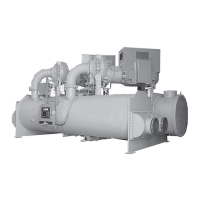
¨ 1. Inspect the unit for shipping or installation damage.
¨ 2. Assure that all piping has been completed.
¨ 3. Assure that the Splicing Kit is properly installed.
¨ 4. Assure that the Communications Cable between
the two control panels is properly installed.
¨ 5. Assure that the Mixed Water Temp. Sensor is in-
stalled properly.
¨ 6. Check that the unit is properly charged and that
there are no piping leaks.
¨ 7. Suction and discharge stop valves and the refrig-
erant liquid stop valves are open (ccw).
CAUTION: Compressor lubrication circuit must be
primed with YORK C oil prior to start-up.
Priming should be done through the
Schrader fitting at the compressor oil pump.
Stroke oil pump 10 times to prime the lubri-
cation circuit.
¨ 8. The compressor oil level must be maintained in the
sight glass at all operating conditions. At part load
operating conditions, it is not abnormal for the oil
level to be in the lower sight glass. If it is neces-
sary to add oil, connect a YORK oil pump to the oil
charging valve, but do not tighten the flare nut on
the delivery tubing. With the bottom (suction end)
of the pump submerged in oil to avoid the entrance
of air, operate the pump until oil drips from the flare
nut joint, allowing the air to be expelled, and tighten
the flare nut. Open the compressor oil charging
valve and pump in oil until the oil reaches the proper
level as described above. Close the compressor oil
charging valve.
¨ 9. Assure water pumps are on. Check and adjust
water pump flow rate and pressure drop across
cooler.
¨10.Check both panels to see that they are free of for-
eign material (wires, metal chips, etc.).
¨11. Visually inspect wiring (power & control). Must
meet NEC and all local codes. (See Figs. 22 and
24)
¨12.Check for proper size fuses in main and control
power circuits.
¨13.Verify that field wiring matches the 3-phase power
requirements of the compressor. See nameplate.
(See Fig. 22)
¨14.Assure 115VAC Control Power to each TB1 has
30A minimum capacity. (See Fig. 22)
¨15.Be certain all control bulbs are inserted completely
in their respective wells and are coated with heat
conductive compound.
PANEL CHECKS
(POWER ON-BOTH SYSTEM SWITCHES OFF)
¨ 1. Apply 3 phase power and verify its value at each
pair of compressor contacts. (See Fig. 22)
Record the voltage: fA _____________ VAC
fB _____________ VAC
fC _____________ VAC
¨ 2. Apply 115VAC and verify its value on the terminal
block in the lower left of each Power Panel. Make
the measurement between terminals 5 and 2.
Should be 115VAC ±10%. (See Fig. 22)
Record the voltage: _______________VAC
¨ 3. Assure crankcase heaters are on. Allow crank-
case heaters to remain on a minimum of 24 hours
before start-up. This is important to assure no re-
frigerant is in the oil at start-up!
JOB NAME: _______________________________________
SALES
ORDER#: _________________________________________
LOCATION ________________________________________
SOLD BY: _________________________________________
INSTALLING ______________________________________
CONTRACTOR ____________________________________
START-UP: _______________________________________
TECHNICIAN/
COMPANY: _______________________________________
DATE: ____________________________________________
CHILLER
MODEL #: _______________________________________
SERIAL #: _______________________________________
COMPRESSOR #1
MODEL #: _______________________________________
SERIAL #: _______________________________________
COMPRESSOR #2
MODEL #: _______________________________________
SERIAL #: _______________________________________
 Loading...