12
2.5 ELECTRICAL ENCLOSURE ASSEMBLY
The unit has two electrical enclosures, one for the generator engine’s control and the other serves as the unit’s main control
panel. The main unit control panel enclosure is designed with hinged access door and according to NEMA 4 requirements. The
internal power and control wirings are neatly routed and with cable markers for identification as per NEC regulation.
The engine’s control panel has the following monitoring devices:
a) Engine hour meter gauge
b) Engine oil pressure gauge
c) Engine temperature gauge
d) Fuel gauge
e) Coolant level gauge
f) Ammeter
g) Voltmeter
h) Frequency meter
The main unit’s control panel has the following control devices:
a) Unit (engine) start / stop switch
b) Vent / Cool selector switch
c) Cool mode selector switch
d) Panel lamps for unit status indications
e) User interface control board
f) Re-set button
g) Lamp test button
h) Emergency stop push button switch
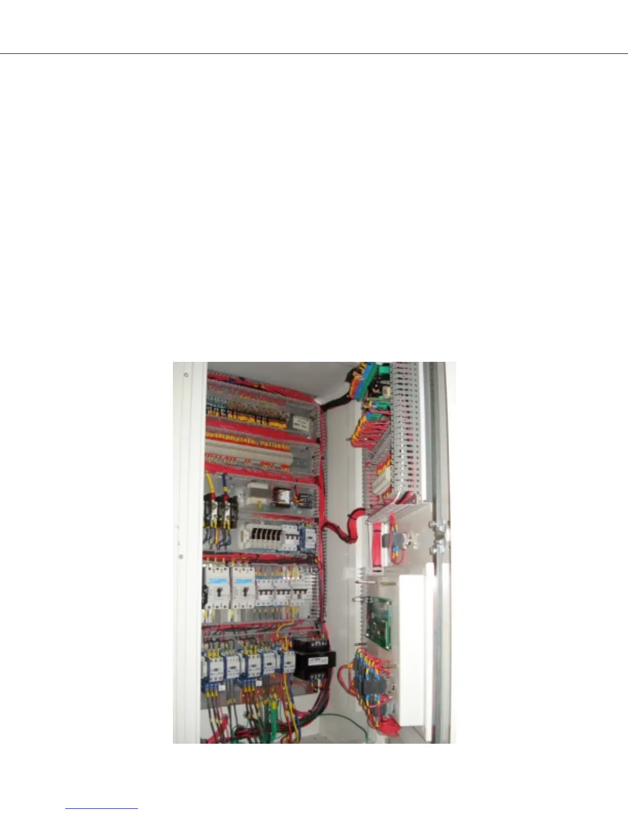
ELECTRICAL ENCLOSURE
(MAIN CONTROL BOX)