15
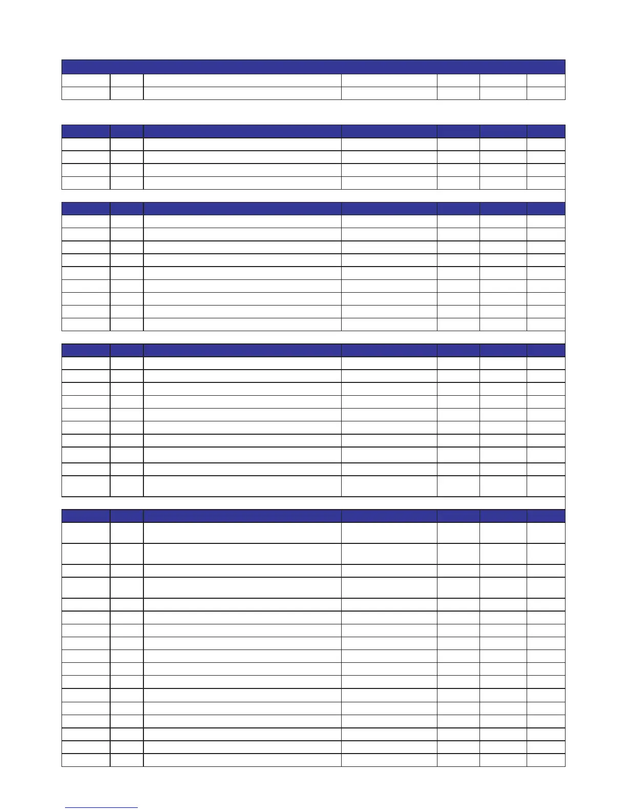
Parameters table DFZ Standard
PSWUTE 4 Password Driver 0 65535
PSWCOST 11 Password Service 0 65535
Regulation parameters
Code Value Description Control cab message MIN MAX UDM
dF1 2,0
Diesel running temperature differential Diesel differential 1,0/1 10,0/50 °C/°F
dF2 2,0 Stand-by running temperature differential Electrical standby differential 1,0/1 10,0/50 °C/°F
min -30,0 Minimum temperature set point Minimum set point -50,0/-58 MAS °C/°F
MAS 25,0 Maximum temperature set point Maximum set point Min 50,0/122 °C/°F
Defrosting parameters
Code Value Description Control cab message MIN MAX UDM
tEb 60
Temperature alarm exclusion time after defrosting end Temp alarm delay 0 999 Minut
tMS 15 Maximum defrosting time Maximum duration 1 60 Minut
tPS Airs Defrosting type Defrost type probe clixon
tFS 12,0 Defrosting end temperature End Defrost Temp. 5,0/41 20,0/68 °C/°F
tSS 120 Time between following defrostings Defrosts interval 1 999 Minut
btS NO Block of desplayed temperature during defrosting Temp. Lock no si Flag
tGo 0 Dripping time Dripping time 0 99 Minut
Svb OFF Fans state during defrosting Fans status ON OFF f ag
trE 1 Evaporator fans starting delay after defrosting end Fans delay 0 99 Minut
Alarm parameters
Code Value Description Control cab message MIN MAX UDM
AH 50,0
High temperature alarm High Temperature 0,0/-58 99,0/210 °C/°F
AL 50,0 Low temperature alarm Low Temperature 0,0/-58 99,0/210 °C/°F
Ad 2,0 alarm differential? Alarm Differential 0,0/-58 99,0/122 °C/°F
rAo 15 Oil alarm exclusion time after starting Oil alarm delay 0 999 Sec
tRA 10 Starting delay after engine water temperature resetting Reset water alarm 0 999 sec
tRO 10 Starting delay after microdoorswitch alarm resetting Restart door microswitch 0 999 sec
tAB 10 Starting alarm presence time Starting Alarm Delay 0 99 Sec
tEr 120 temperature alarm exclusion time after starting Temp alarm delay 0 999 Minut
tPO 10 Starting delay after pressure switches and battey alarms resetting Press/batt reset 0 999 sec
tbm 10
Maximum time below minimum tension, allowed before relative
alarm displaying Low battery delay 0 999 sec
Starting parameters
Code Value Description Control cab message MIN MAX UDM
Vbm 11,0
minimum bat
tery voltage allowed before automatic switching to
continuos running mode Min. battery voltage 0 20,0 V
Vam 10,0
Minimum alternator voltage allowed during temperature
regulation phase Reg. alt. Voltage 0 13,0 V
VAM 11,0 Minimum alternator voltage allowed during starting Starting alt. Voltage 0 13,0 V
VEM 12,0
Minimum alternator voltage allowed during starting and running
in stand-by mode Electrical alt. Voltage 0 13,0 V
nga 0 Rpm during starting Starting Rpm 0 5000 100*rpm
ngf 0 Rpm during regulation Running Rpm 0 5000 100*rpm
ngd 0 Rpm difference between the two revolutions counter Running Rpm 0 5000 100*rpm
SPr SI Pre-heating probe presence Sensor pre-heating presence NO SI f ag
tPr 15 Pre-heating time pre-heating time 0 99 Sec
Ct1M 32 Maximum delay before regulation Max delay reg. 0 999 sec
Ct1m 12 Minimum delay before regulation Min delay reg. 0 999 sec
Tmax 60,0 Maximum temperature detectable from water probe Water Max Temp. -55,0/-67 11,0/230 °C/°F
Tmin 0,0 Minimum temperature detectable from water probe Water Min. Temp. -55,0/-67 11,0/230 °C/°F
Ct1 30 Regulation phase delay after starting Regulation delay 1 100 Sec
tPA 6 Starting procedure allowable time Starting process time 1 240 Sec
tmo 0 Minimum running time Minimum Time 0 999 sec
tPM 5 Starting attempts number Start attempt 0 10
2. Parameters table of programming