EasyManuals Logo

ZAPTEC Go User Manual

ZAPTEC Go
240 pages
To Next Page IconTo Next Page
To Previous Page IconTo Previous Page
Page #88 background imageLoading...
Page #88 background image
88
Deutsch
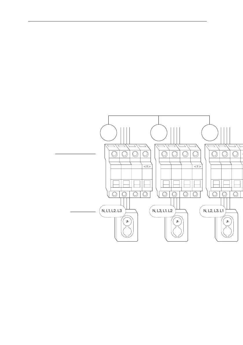
10. Installation mehrerer Ladegeräte
Maximaler Gesamtstrom 32A
Schutzschalter und
RCD Typ A.
Muss bei Installationen mit
mehreren Zaptec Go
gleichwertig sein.
Ein Leistungsschalter und
RCD Typ A pro Zaptec Go.
Phasendrehung für bessere
Lastverteilung beim
1-Phasen-Laden
Integrierter Fehlerstrom-
schutz RCD-DD (6mA DC)
nach IEC 62955
40A 40A 40A
3-Phasen-Installation
3 Phasen für Ladegeräte
N, L1, L2. L3 N, L3, L1. L2 N, L2, L3. L1
Bei rotierenden Phasen einer 3-Phasen-Installation müssen Sie mit der Zaptec-App angeben,
welche eingehende Phase (L1, L2 oder L3) mit der Phase-1-Klemme am Ladegerät verbunden
ist. Dies kann nur über die „Install Zaptec Go“-Reise in der Zaptec-App erfolgen.

Other manuals for ZAPTEC Go

Questions and Answers:

Question and Answer IconNeed help?

Do you have a question about the ZAPTEC Go and is the answer not in the manual?

ZAPTEC Go Specifications

General IconGeneral
TypeElectric Vehicle Charger
Charging Power22 kW
Weight1.3 kg
Protection RatingIP54
Charging StandardIEC 61851-1
Maximum Charging Power22 kW
Protection ClassClass I
Current Output32A
ConnectivityWi-Fi, Bluetooth
Operating Temperature-30°C to +40°C
Input Voltage230/400V AC
Cable LengthNot included

Related product manuals