MAIN MOVING SYSTEM EM -45
DISASSEMBLY E A7E6C0F
1. Remove the timing belt, front case, flywheel, cylinder
head assembly and oil pan. For details, refer to the
respective chapters.
2. Remove the rear plate and the rear oil seal.
3. Remove
the connecting rod caps.
4. Remove the main bearing caps and remove the crank-
shaft.
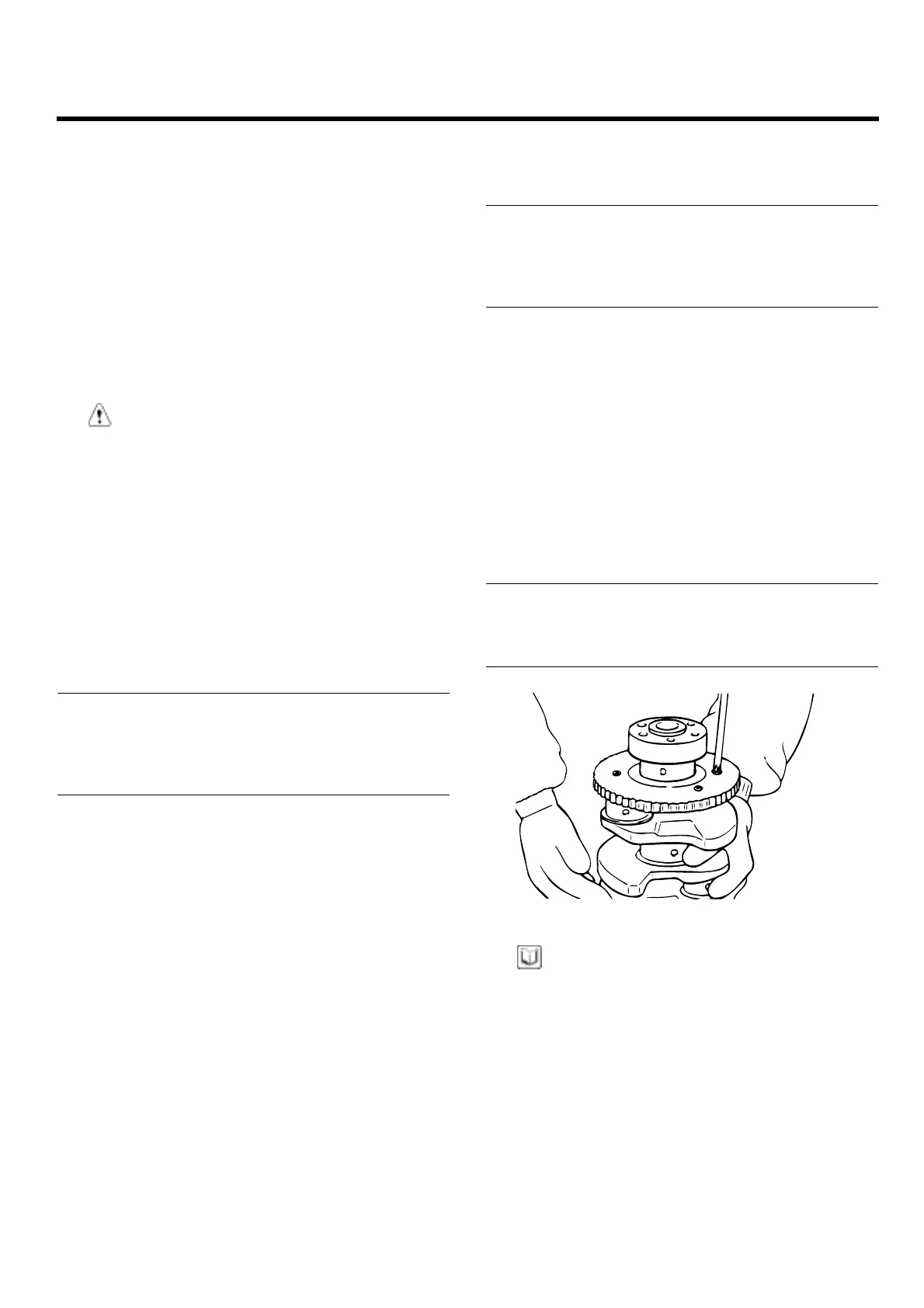
5. Remove the crankshaft position sensor wheel.
CAUTI
ON
Mark the main bearing caps to permit reassembly
in the original position and direction.
INSPE
CTION
E76DB219
CRANKSHAFT
1. Check the crankshaft journals and pins for damage,
uneven wear, and cracks. Also check oil holes for
clogging. Correct or replace any defective part.
2. Inspe
ct the crankshaft journal for taper and out - of -
roun
d.
Standard value
Crankshaft journal O.D : 50 mm (1.9685 in.)
Crankshaft pin O.D : 45 mm (1.7717 in.)
Crankshaft journal, pin out-of-roundness and taper :
0.005 mm (0.0002 in.) or less
MAIN BEARINGS AND CONNE CTING ROD
BEARINGS
Visually inspect each bearing for peeling, melting, seizure,
and improper contact. Replace the defective bearings.
OIL CLEARANCE MEASUREMENT
1. Measure the diameter of the crankshaft journal and
pin.
2. Measure the diameter of the crankshaft bore and con-
necting rod bore.
3. Measure the thickness of the crankshaft bearing and
connecting rod bearing.
4. Measure the clearance by the value that subtract the
diameter of journal and pin and the thickness of bear-
ing from the diameter of bore.
Connecting rod bearing oil clearance :
0.018 ~ 0.036 mm (0.0007 ~ 0.0014 in.)
Crankshaft main bearing oil clearance
NO. 1,2,4,5 : 0.022 ~ 0.040 mm (0.0009 ~ 0.0018 in.)
NO.3 : 0.028 ~ 0.046 mm (0.0011 ~ 0.0018 in.)
OIL SEAL
Check front and rear oil seals for damage or wear. Replace
any seal that is defective.
CRANKSHAFT SENSOR WHEEL
1. Remove the sensor wheel.
2. Chec k the sensor wheel for damage, cracks and wear,
and replace if necessary.
3. Chec k the clearance between the sensor wheel and
the crank position sensor with a depth gage.
Standard value
Clearance between sensor wheel and crank
position sensor :
0.5 ~ 1.1 mm (0.020 ~ 0.043 in.)
EDDA028C
NOTE
1. Measure the depth of the top of sensor wheel
tooth and the cylinder block mounting block.
2. Measure the difference between sensor length
and depth.
3. Sensor length is the distance between the end of
the sensor and the inner point of the contacting
face.
ZENITH POWER PRODUCTS - 416