CYLINDER HEAD ASSEMBLY EM -33
DISASSEMBLY E BCFA4C6
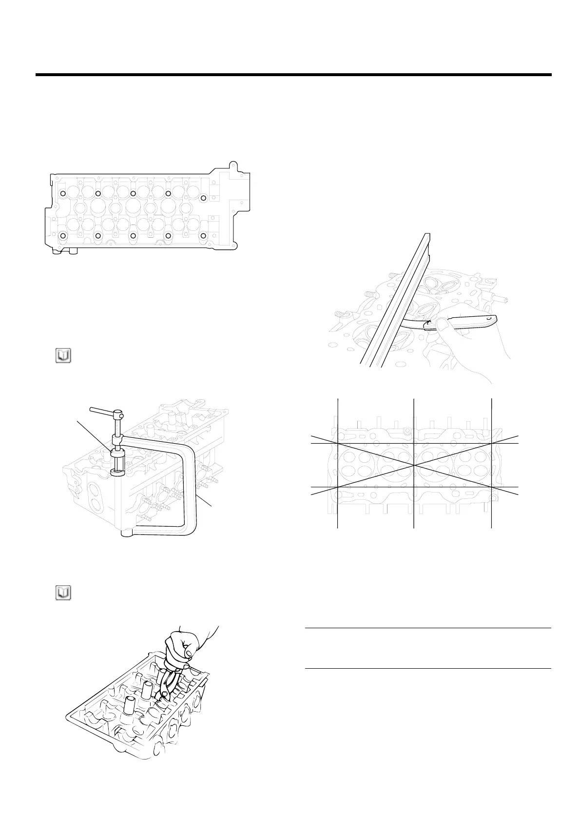
1. Using a tool remove the cylinder head bolts in the
order shown in the illustration.
3 5 10 8 2
1 7 9 6 4
EDKD115A
2. Usin
g the special tool (09222-28000, 09222-28100),
remo
ve the valve retainer lock. Next remove the
spri
ng retainer , valve spring, spring seat and valve.
NOTE
Arrange these parts so that they can be reinstalled in
their original positions.
09222-28100
09222-28000
EDKD116A
3. Remove the valve stem seals with pliers.
NOTE
Do not reuse the valve stem seals.
EDDE088B
INSPECTION EE4FDB50
CYLINDER HEAD
1. Check t
he cylinder head for cracks, damage and
coolan
t leakage. If crack ed, replace the cylinder
head.
2. Remove scale, sealing compound and carbon deop-
sits completely. After cleaning the oil passages, ap-
ply compressed air to verify that the passages are not
clogged.
ECKD001H
3
.
C
heck the cylinder head surface for flatness in the di-
r
ection as shown in the illustration. If flatness exceeds
t
he service limit in any direcftion, either replace the
cylinder head or machine the cylinder head matching
surface lightly.
Flatness of cylinder head gasket surface
Standard : Less than 0.03 mm (0.0012 in.)
Limit : 0.05 mm (0.002 in.)
ZENITH POWER PRODUCTS - 416