LOOP 500
3
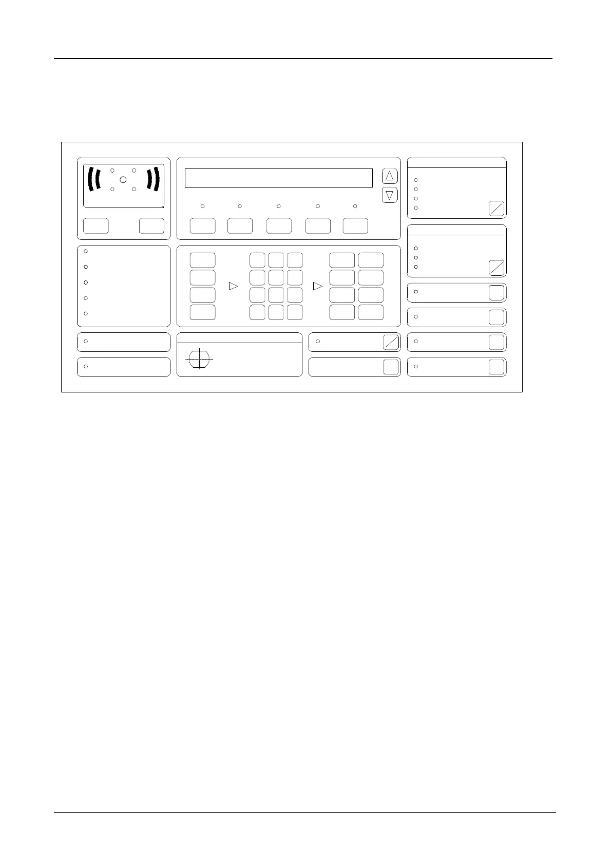
Control and indicating unit of LOOP 500 control panel,
Model GB
LAMP TEST
DAY MODE
TEST MODE
CHARGER FAILURE
PROZESOR FAULT
ISOLATED
POWER ON
ACCESS
FAULT
TEST MODE
Buzzer
Silence
FAULT
Function
Special
Zone
Reset
ALARM
1
0
4
7
*
2
C
3
5
8
6
9
On
ISOLATED
Off
On
Off
On On
EMERGENCY ALARM
ACTIVE
NORMAL
ENABLE
FIRE
Select
CONTROL
SOUNDERS SILENCED
SOUNDERS ON
SOUNDERS FAULT
ACTIVATED
ISOLATED
On
Off
On
Off
FAULT
REMOTE SIGNAL
ALARM STATUS
Select
Output
ALARM COUNTER
View Alm View Flt View Act View Isol View Test
Test Test
On Off
Select
Controls
Off
ALARM DELAY OFF
ALARM ACKNOWLEGED
Silence
Alert
Sounders
Evacuate
1. Overview
1.1. General
The LOOP 500 control panel is a detector control and indicating equipment for connection of a maximum of
504 conventional addressable detectors.
1.2. Operator control levels
Operation of the LOOP 500 control panel is divided into four operator control levels. The current status is
indicated on the display. The transition between individual operator control levels is documented in the
event memory.
Operator control level 1
The 1st operator control level is always accessible; on this level, it is possible to cancel the internal audible
signal, to carry out the lamp test, to display the alarm counter and to recall the concealed (behind the
display) messages on the display.
Operator control level 2
The 2nd operator control level can be accessed by means of a key (turn key towards OPERATION
ENABLED). On this operator control level it is possible to disable and enable the detectors, the zones, the
transmission unit, the output for the external audible signalling units, control loops and fire alarm devices, to
carry out day/night switching, to reset the control panel and to display the event memory.
Operator control level 3
The 3rd operator control level can be accessed after entering the password (max. 8 digits) on the 2nd
operator control level. On this operator control level it is possible to set individual detectors or zones to
inspection mode, to exit inspection mode, to change the time switch controls (only the switching times, not
the linkages), to enter time of day and date, to alter the delay and to enter or alter the password.
Operator control level 3a
The operator control level 3a can only be accessed with an electronic key (Order No.: 571.026). On this
operator control level it is possible to carry out cold and warm start and to modify the configuration data via
the RS232 serial interface (from the programming station).
http://www.firealarmengineers.com