Maintenance and Installation Instructions Edition 11.07.2006 18 of 30
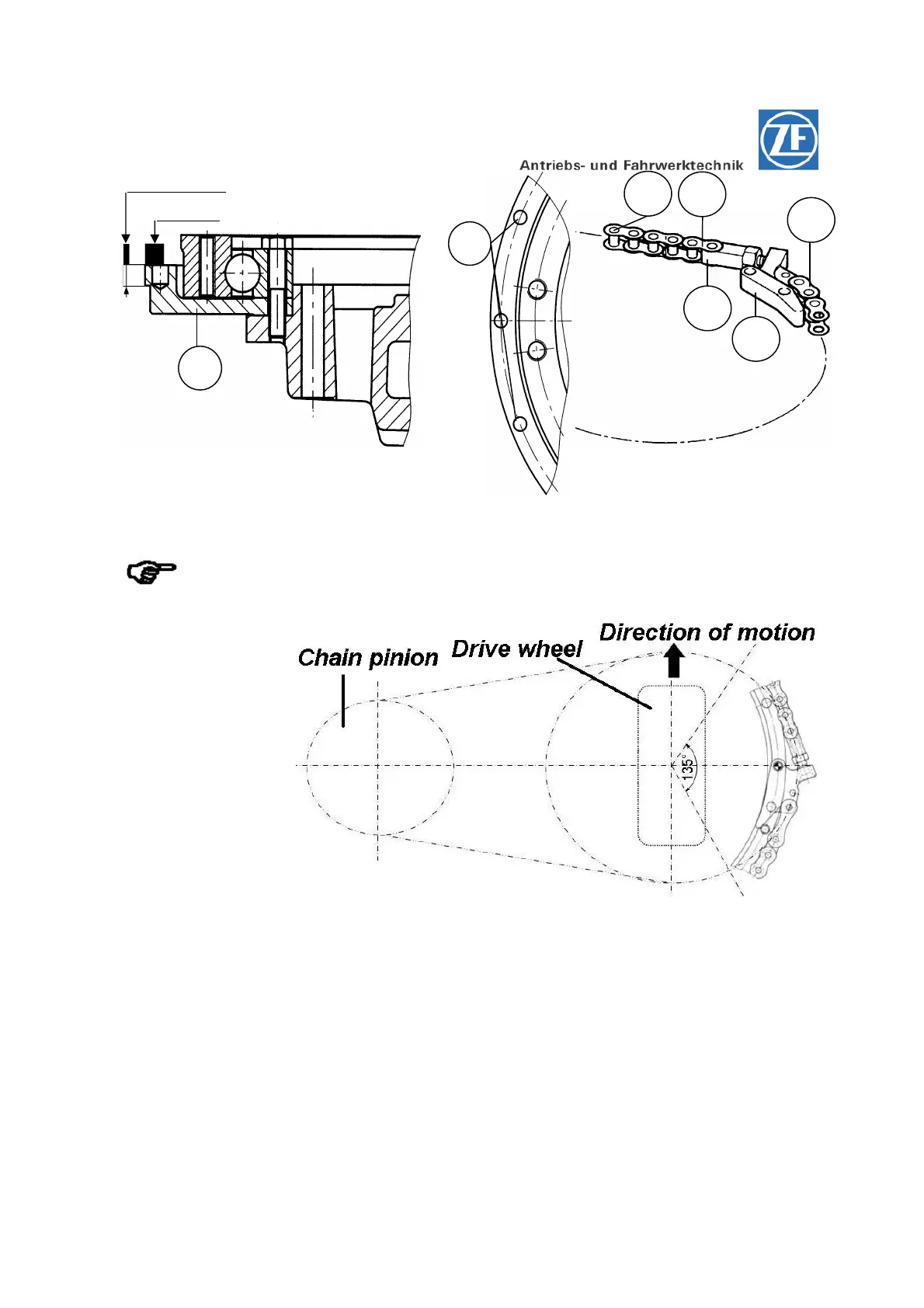
Figure 13
Within an area of approx. 135° around the chain tensioner only riveted
connecting elements (chain joints) are allowed to be used.
Drive wheel and wheel
shaft respectively must
be aligned in direction of
motion.
The chain tensioner
should be mounted
opposite of the steering
pinion. This ensures that
there is an equal steering
angle towards both sides.
Figure 14
Mounting of the pivoted connection
(see Fig.05, Page 12)
1. The centering and supporting face for the chain flange has to be clean.
2. Pay attention that no foreign substances or cleaning agents get through the threaded holes (Item
01) of the mounting construction (hole pattern of the housing) inside the transmission.
3. Place the chain flange (Item 02) and rotate it, so that the boltholes in the chain flange are aligned
with the threaded holes of the mounting construction.
4. By means of a plastic tip hammer install the chain flange until contact is obtained.
5. Put on the pivoted bogie bearing (Item 03) with the correct side and rotate it so that the boltholes
in the pivoted bogie bearing are aligned with the hole pattern of the flange and the housing.
6. Fasten the pivoted bogie bearing and the chain flange on the mounting construction by means
hexagon screws M8x40 (Item 04).
02
Plane face
07
04
06
03
01
05