MXK
20 MxK Hardware Installation Guide
In the 8U chassis the two middles slots, slots a and b, are only for the uplink
cards. There are 7 or 9 line cards on either side of the uplink cards depending
on the chassis size. Any type of line card can be installed in those slots.
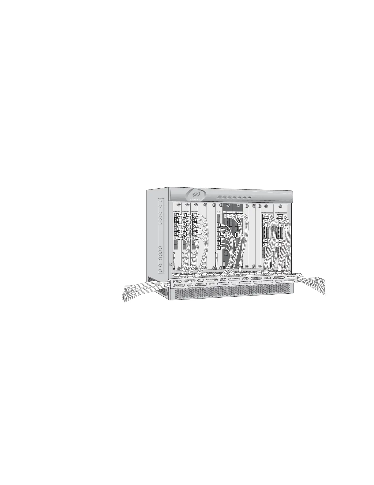
Cables and connectors are accessed from the front of the chassis. The MXK
provides a metal harness on the front of the chassis for easy cable
management as shown in Figure 3.
Cables and connectors (except for power cables) are accessed from the front
of the chassis as shown in Figure 3. For the MXK 819, power cables enter the
device at the lower right front of the unit. Power for the MXK 823 is provided
on both the front of the chassis and the rear of the chassis. Both power
supplies are supplied by dual –48V DC input power. The airflow through the
unit is from bottom to top. The chassis is FCC, UL, CSA, and CE compliant.
See Connect power to the front of the MXK and ground the chassis on page 42
or Connect power to the rear of the MXK 823 and ground the chassis on
page 47 for connecting power instructions.
Figure 3: MXK chassis with cables and connectors
Figure 5 shows the 23” MXK chassis with 18 line cards and two uplink cards.
mx0702
active
fault
pwr fail
1
2
3
4
1
0
G
IG
E
U
P
L
IN
K
C
R
A
F
T
M
G
M
T
X
FP
X
P
P
active
fault
pwr fail
1
2
3
4
1
0
G
IG
E
U
P
LIN
K
C
R
A
F
T
M
G
M
T
X
F
P
X
P
P
active
fault
pwr fail
GPON
8 - SFP
1
2
3
4
5
6
7
8
active
fault
pwr fail
GPON
8 - SFP
1
2
3
4
5
6
7
8
active
fault
pwr fail
GPON
8 - SFP
1
2
3
4
5
6
7
8
active
fault
pwr fail
GPON
8 - SFP
1
2
3
4
5
6
7
8
1
2
3
4
5
6
12
13
14
15
16
17
18
19
20
21
22
7
8
9
10
11
ACTIVE
ETHERNET
active
fault
pwr fail
1
2
3
4
5
6
12
13
14
15
16
17
18
19
20
21
22
7
8
9
10
11
ACTIVE
ETHERNET
active
fault
pwr fail