System Cables and Connectors
56 MXK Hardware Installation Guide
Cable descriptions
Table 8 lists specifications for the cables used with the MXK system. For
pinout information for these cables, refer to the chapters for each card, later in
this manual.
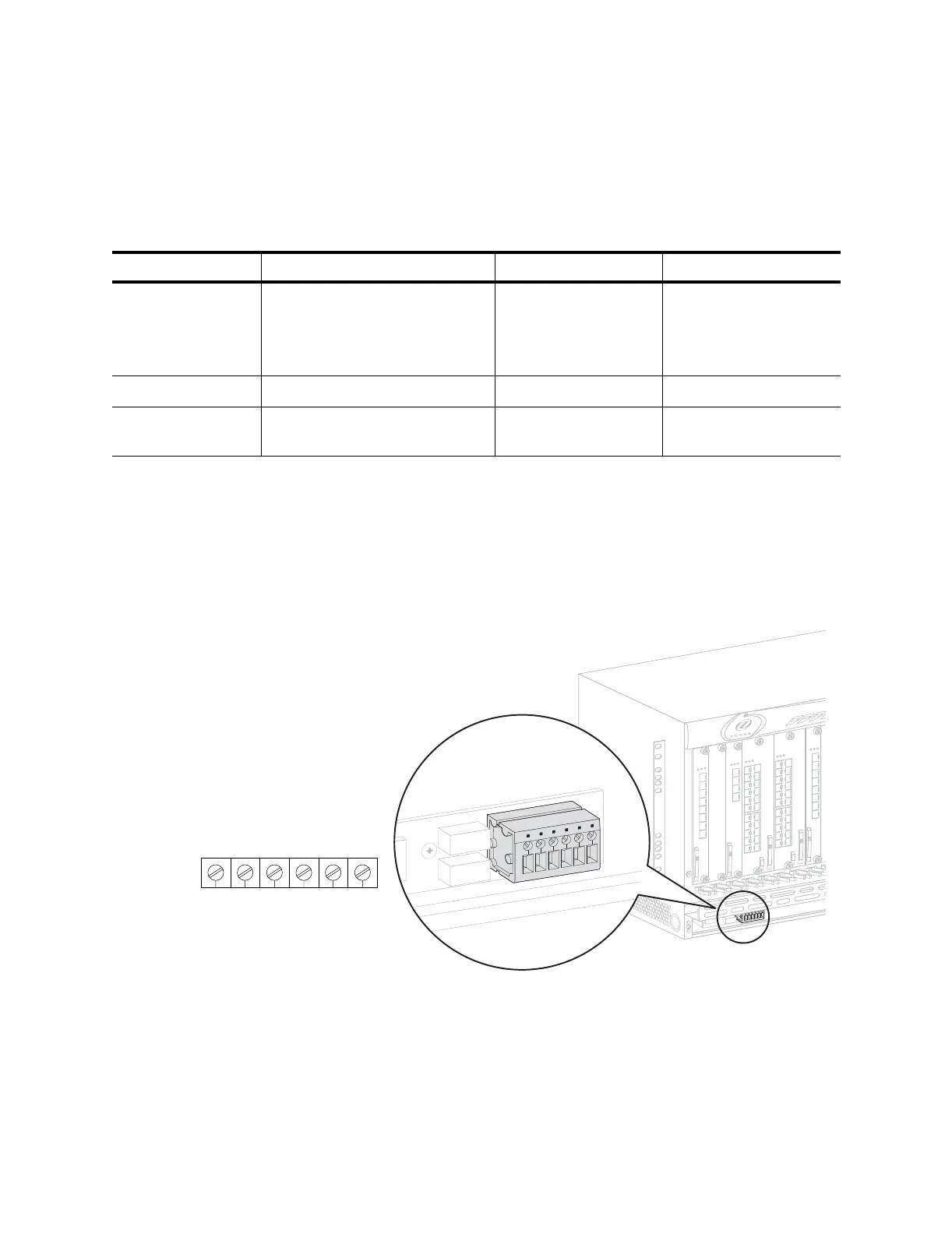
MXK alarm cable and contacts guidelines
The MXK 819 and MXK 823 chassis alarms are located in the lower left of
the chassis, behind the bezel. See Figure 27.
Figure 27: MXK chassis alarms
When alarms are present, the connections are as follows:
• When a critical alarm is present, there is a connection between J1-J2.
• When a major/minor alarm is present, there is a connection between
J4-J5.
• When a critical alarm is present, there is no connection between J2-J3.
Table 8: Summary of cable specifications
Cable description Interfaces the MXK to Cable type Connector type
Chassis alarms Alarm relay contact on chassis
(MXK 823 or MXK 819)
Alarm relay contact on TAC/
Ring-FC card
20 AWG minimum (0.8
mm)
24 AWG (0.5 mm)
recommended
Blank wire in to screw
terminals.
Management (IP) Ethernet port on uplink card. 4 pair Category 5 RJ45 plug
Management (serial
craft port)
RS-232D connector on uplink
card.
4-wire minimum
26 AWG (0.4 mm)
RJ45 plug
J1 J2 J3 J4 J5 J6
Open
critical alarm
Common
Closed
critical alarm
Open
major/minor alarm
Closed
major/minor alarm
Common
mx0715