MXK alarm cable and contacts guidelines
MXK Hardware Installation Guide
57
• When a major or minor alarm is present, there is no connection between
J5-J6.
When alarms are not present the connections are as follows:
• There is no connection between J1-J2 or J4-J5.
• There is a connection between J2-J3 and J5-J6.
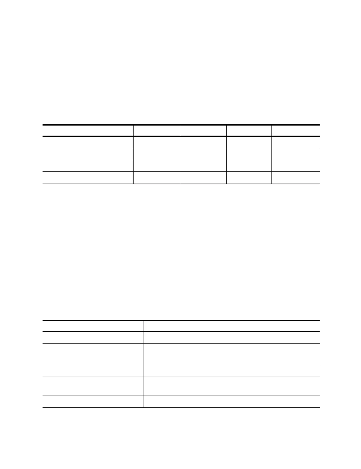
Table 9 describes the MXK alarm states.
The specifications and requirements for the MXK chassis alarm cable and
alarm relay contacts are as follows:
• The alarm cable must be rated at VW-1 or higher. To comply with Part 15
of FCC regulations, all cables to DB connectors must be foiled with
braided shielding.
• One cable is required to interface to the alarms connector. The minimum
gauge for this cable is 20 AWG (24 AWG recommended). To limit alarm
cable signal losses, its length should not exceed 60 feet.
• Alarm relay contacts are rated at 62.5 VA (defined as being capable of
switching 1 amp at 62.5 volts). The maximum switching current of the
relay is 1 amp.
Table 10 to Table 14 describe the MXK chassis alarms.
Table 9: MXK alarm connections table
Alarm state J1–J2 status J2–J3 status J4–J5 status J5–J6 status
Critical alarm not present open closed X X
Critical alarm is present closed open X X
Major/minor alarm is not present X X open closed
Major/minor alarm present X X closed open
Table 10: System alarms
Event Type of alarm
Fan Tray up/down Critical
Power A/B up/down Critical (if nonredundant)
Minor (if redundant)
System control bus error Critical
Power Threshold (power out of
acceptable range)
Minor
Thermal threshold Minor