Instructions. V1.01 Page 8 JUNE / 2013
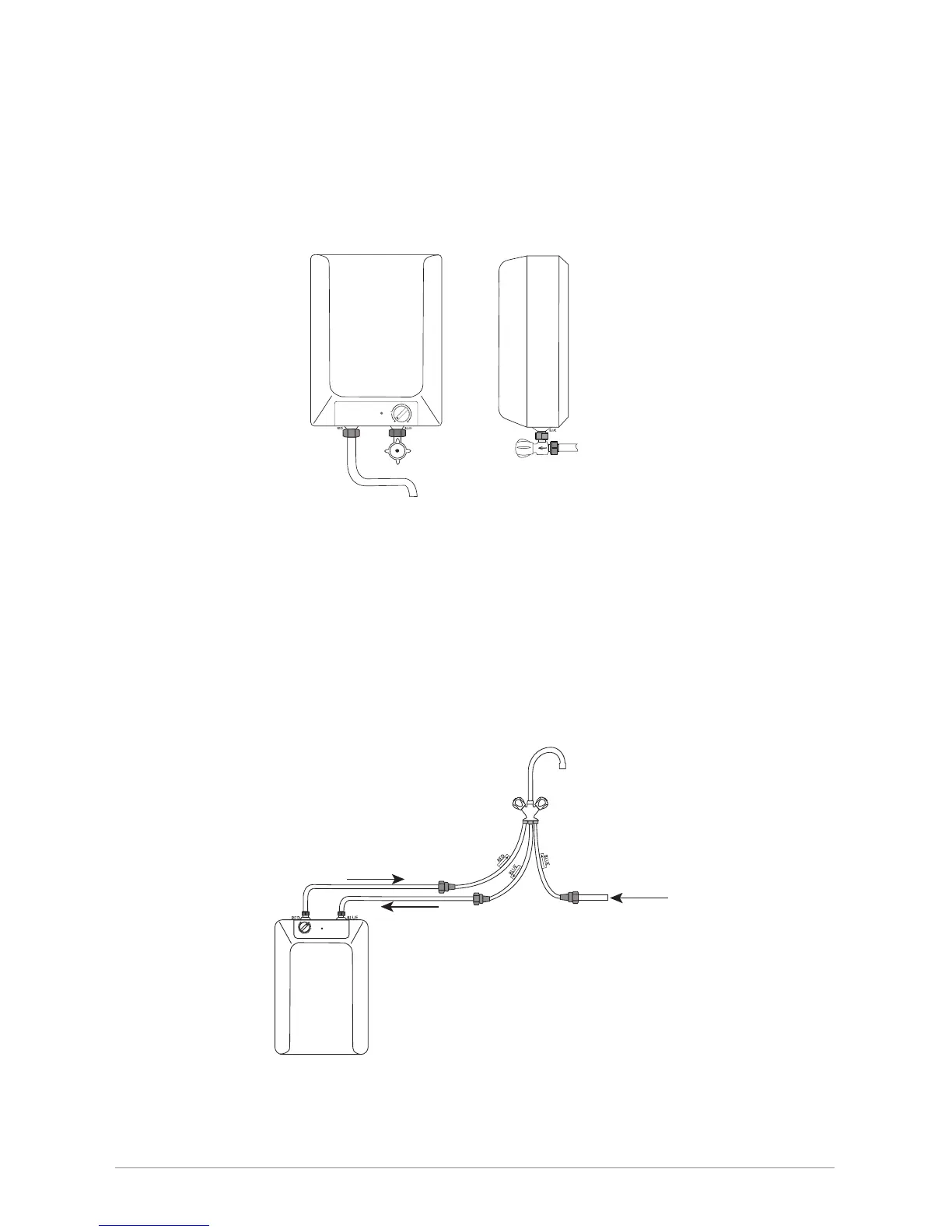
Overbasin Installation.
The inlet control valve supplied incorporates compression ttings suitable for tting
between 15mm copper piping (water supply) and the inlet connection (coloured blue)
situated on the water heater.
Fit the control valve to the cold water supply ensuring that the water will ow in the
direction of the arrow indicated on the side of the control valve (g.2a).
Do not over tighten the compression joints but ensure that these are leak free.
WATER
SUPPLY
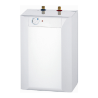
ZIP Tudor II
g. 2
g. 2a
MAINS
Supply
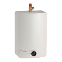
ZIP
Tudor II
Cold (Supply In)
Hot to Tap
ZIP Approved
Vented Tap
Underbasin Installation.
In all underbasin installations the outlet must be connected to an open outlet type
fitting approved by Zip heaters.
The diagram below (fig 3) shows a typical installation of a monobloc mixer tap
assembly, product ref. UB1. Alternative Zip approved products are product ref. UB6
and UB7.
NOTE:
When installing underbasin models it is recommended that bre washers are used on
both inlet and outlet connections to ensure a watertight seal.
Connect mains supply to the ‘blue’ tag tail (arrow pointing UPWARD). The inlet ‘blue’
connection on the heater is connected to the ‘blue’ tag tail (arrow pointing DOWNWARD).
The outlet connection of the heater ‘red’ is connected to the ‘red’ tag tail (arrow pointing
UPWARD).
g.3
 Loading...