7. If you are installing the Ei chlorine generator
on a DN50 mm type pipe, insert the reducer
bearing the ‘EU’ mention into the paddle clamp
lower part (Use the other reducer for a 1 1/2 ‘’
pipe). Important: make sure that the adapter fi ts
correctly into the notches located on the lower
part of the paddle clamp (4).
8. Click the lower part of the paddle clamp onto the
upper part already in place on the pipe (5).
9. Ensure that the O’ring is correctly positioned, then
fi t the Ei electrode on the paddle clamp.
Note: the electrode has a direction and can only be
inserted in one way (use the foolproof notch) (7).
10. Tighten the locking ring (Hand only tightening!)
on the paddle clamp.
Make sure you respect the thread direction - it
should screw on easily.
11. Connect the cell wire to the Ei electrode connectors by
following the colour code between connectors, male and
female, as indicated below (Red to red, black to black and
blue to blue).
12. Place the cover back on the Ei electrode and slide the
wire in the slot designed for this purpose located on the
side of the electrode (8).
3.3 Flow meter installation
The fl ow meter and its paddle clamp (DN50 mm) must be
installed on the piping close to the Ei cell and upstream from it.
> Ei cell installed on-line: the fl ow meter MUST be installed
right next to the cell and after the valve (if any) (1).
>
Ei cell installed on a by-pass: The fl ow meter MUST be
installed on the cell by-pass between the upstream cut-off
valve and the cell itself.
W A R N I N G : Non compliance with these instructions
may result in damage to the cell (See diagrams) (2)!
IMPORTANT NOTE: The fl ow meter has a direction
(Arrow indicating the water fl ow direction).
Make sure that it is properly positioned on its paddle clamp
in order to stop the Ei chlorine generator production when
the fi ltering is not operating (‘Flow’ red alarm lit to be
interpreted as a lack of fl ow).
Once the fl ow meter is installed on the paddle clamp (use Tefl on tape on the screw-thread to ensure
watertightness), connect the wiring to the Ei power pack using the quick ‘JACK’ plug.
!
!
Notches
(4) (5)
O’ring
(6)
Foolproof notch
(7)
(8)
CORRECT:
(1)
BAD:
(2)
24
3.4 Ei power pack connection
The Ei Zodiac appliance is designed to operate only with a 220-240 Vac 50 Hz. power supply.
IMPORTANT: The installation and use of Ei salt water chlorinators must comply with the instructions and
recommendations presented in this manual. For additional information, please contact your professional
pool retailer.
The Ei chlorinator may be connected in two different ways:
1) Either connected to a permanent power supply using the plug (power supply protected by a 30 mA
g r o u n d f a u l t s w i t c h i n c o m p l i a n c e w i t h N F C 1 5 - 1 0 0 o r e q u i v a l e n t d e p e n d i n g o n e a c h c o u n t r y ) .
2) Either directly subjected to the pool fi lter system (appliance only connected when the fi ltering is
operational).
Le fi rst possibility above is the preferred electric connection.
Once the connections are completed successfully and glue (if any) has set and dried (wait a few
hours depending on the product used), connect to the electrical mains in order to operate the Ei.
Ei salt chlorinator parametering
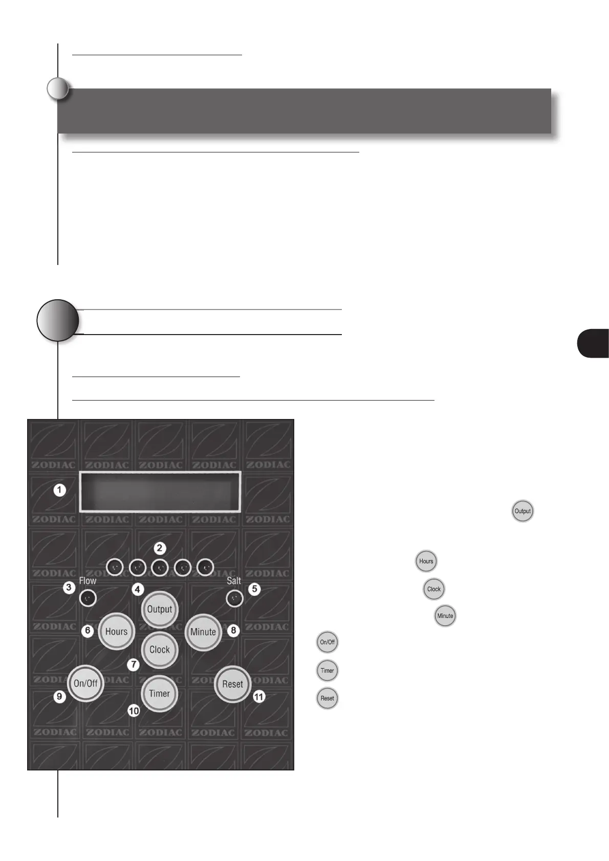
4.1 Ei power pack description
The diagram below shows the functions of your Ei appliance power pack:
1 LCD screen
2 Chlorine production visual indicator (1
st
orange
and 4 others green)
3 Red visual light ‘Flow’ lack of fl ow safety
4 Adjustment of chlorine production button
5 ‘Salt’ lack of salt orange indicator
6 Hours setting button
7 Clock adjusting button
8 Minutes adjusting button
9
button manual “on/off”
10
programmer button
11
reset button
4
The Ei Zodiac appliance is designed to operate only with a 220-240 Vac 50 Hz. power supply.
!
25
EN
 Loading...