4
Monthly
Unit
Recommended
values
To increase To reduce
Test frequency
(in the season)
HL
(level of
calcium
carbonate)
°f (ppm)
10 – 30
(100 – 300)
Add calcium
Add a calcium carbonate
sequestering agent (Calci-)
or carry out carbonate
removal
Monthly
Cyanuric
acid
(stabiliser)
mg/L or
ppm
< 30
Only add cyanuric acid
if necessary (Chlor Stab)
Par ally empty the pool
and refi ll it
Quarterly
Salinity
g/L or kg/
m³
4 Add salt
Leave as such or par ally
empty the pool and refi ll it
Quarterly
Metals
(Cu, Fe, Mn,
etc.)
mg/L or
ppm
± 0 /
Add a metal fi xer
(Metal Free)
Quarterly
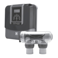
2.2 Installing the power pack
• The power pack box must be installed in a ven lated technical room, free from all traces of damp, free from stored pool
maintenance products and free from freezing temperatures.
• The control box must be installed less than 3.5 metres from the pool.
• It must not be installed more than 1.8 metres from the cell (maximum cable length).
• If the pack is fi xed to a post, a water ght panel must be fi xed behind the control box (350x400 mm minimum).
• Fix the support solidly to the wall or the water ght panel, and place the power pack on it using the screws provided.
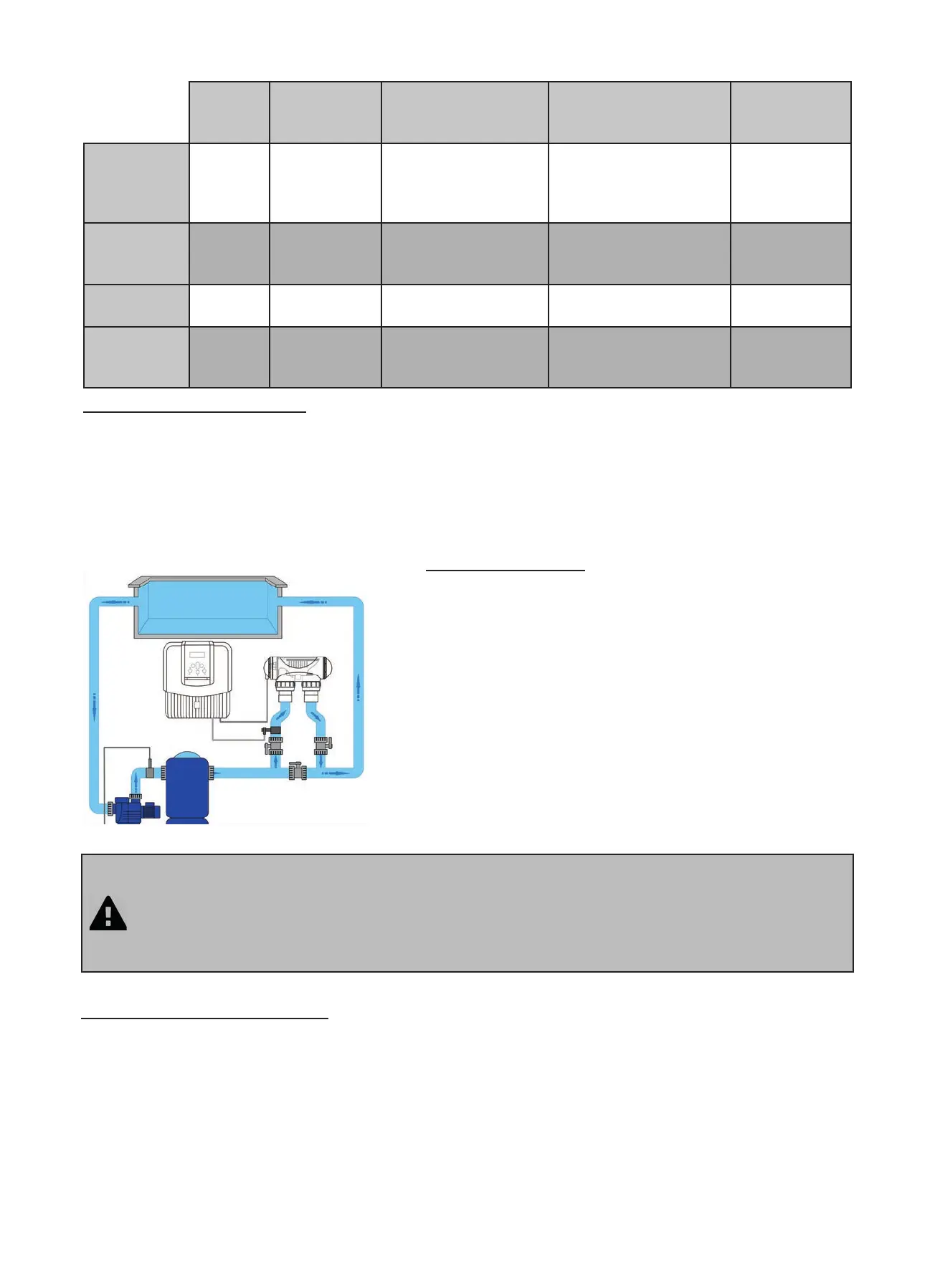
• The cell must always be the last element placed on the pool return pipe (see diagram).
• It is always recommended to install the cell on a by-pass. This assembly is MANDATORY if the fl ow is in excess
of 18 m³/hour to avoid load loss.
• If you installed the cell on a by-pass, it is recommended to fi t a check valve downstream from the cell and not
a manual valve, to avoid any risk of incorrect handling.
• The two red wires can be connected to one or the other red terminals on the electrode.
2.4 Installing the flow controller
The fl ow controller and its fi xture collar (Ø50 mm) must impera vely be installed on the piping close to the cell and
upstream from it. Use the supplied threaded adapter and Tefl on tape to install the fl ow controller on its fi xture collar.
• Cell installed on a by-pass: the fl ow controller must be installed on the cell by-pass between the upstream isola on
valve and the cell itself.
• Cell installed in line: the fl ow controller must be installed just in front of the cell and a er a possible valve.
• Tighten the fl ow controller using the ghtening nut only ( ghten by hand!).
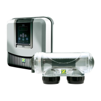
2.3 Installing the cell
• The cell must be installed on the piping a er the fi ltering, a er
any measurement sensors, and a er eventual hea ng systems.
• Make sure that the cell is placed HORIZONTALLY. Ideally the
water should fl ow from the electric connec ons towards the
opposite side.
• Use the screw-on fi ngs to fi x the cell to the pipes. For Ø63 mm
pipes, glue them directly to the screw-on fi ngs. For Ø50 mm
pipes, use glue-on PVC adapters of the corresponding diameter
(grey models; the white models are for 1 ½’’ UK pipes). In the
case of Ø63 mm pipes, glue them directly to the screw-on fi ngs.
• Connect the cell power supply cable following the wire colour
codes (red, black and blue connectors) and then refi t the
protec ve cap.