5
EN
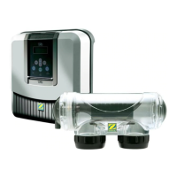
Tightening
nut
• Failure to follow these instruc ons could lead to the destruc on of the cell ! (see “2.3 Installing the cell”). The
manufacturer cannot be liable in this case.
• The fl ow detector has a direc on for installa on (arrow indicated on it showing the fl ow direc on for the
water). Make sure that is is correctly placed on its fi xture collar so that it stops the electrolyser produc on when
fi ltering is stopped (red “Flow” indicator on showing the absence of fl ow, see “5. Troubleshoo ng”).
2.5 Electric connections
2.5.1 Connec ng the power pack
The electrolyser can be connected in several diff erent ways (in compliance with the applicable standards in the country
of installa on).
• Preferred connec on: the appliance is connected to a permanent power supply separated from the fi ltering thanks to
the presence of the fl ow controller (power supply protected by a specifi c 30mA ground fault circuit breaker).
• Possible connec on: directly coupled to the pool fi ltering (the appliance is only supplied with power when fi ltering is
opera ng).
• Op onal connec on: the female connector located under the pack is designed for the direct connec on of a fi ltering
pump (230Vac-50Hz, maximum consump on 9A). In this case, use the supplied corresponding male connector (which
will allow the electrolyser programmer to control both fi ltering and chlorina on mes).
• When all connec ons have been completed and all glued assemblies have dried, reconnect the mains power supply to
power on the appliance.
Whichever connec on is used, it is mandatory to programme the electrolyser opera ng mes (called “Timers”)
(see “3.2.2 Programming Menu (Timers)”).
2.5.2 Connec on to an electric roll-on shu er
If the pool is fi ed with an electric roll-on shu er, it can be connected to the electrolyser so that the la er automa cally
adapts its chlorine produc on when the shu er is closed (see”3.1.2 “Low” mode”).
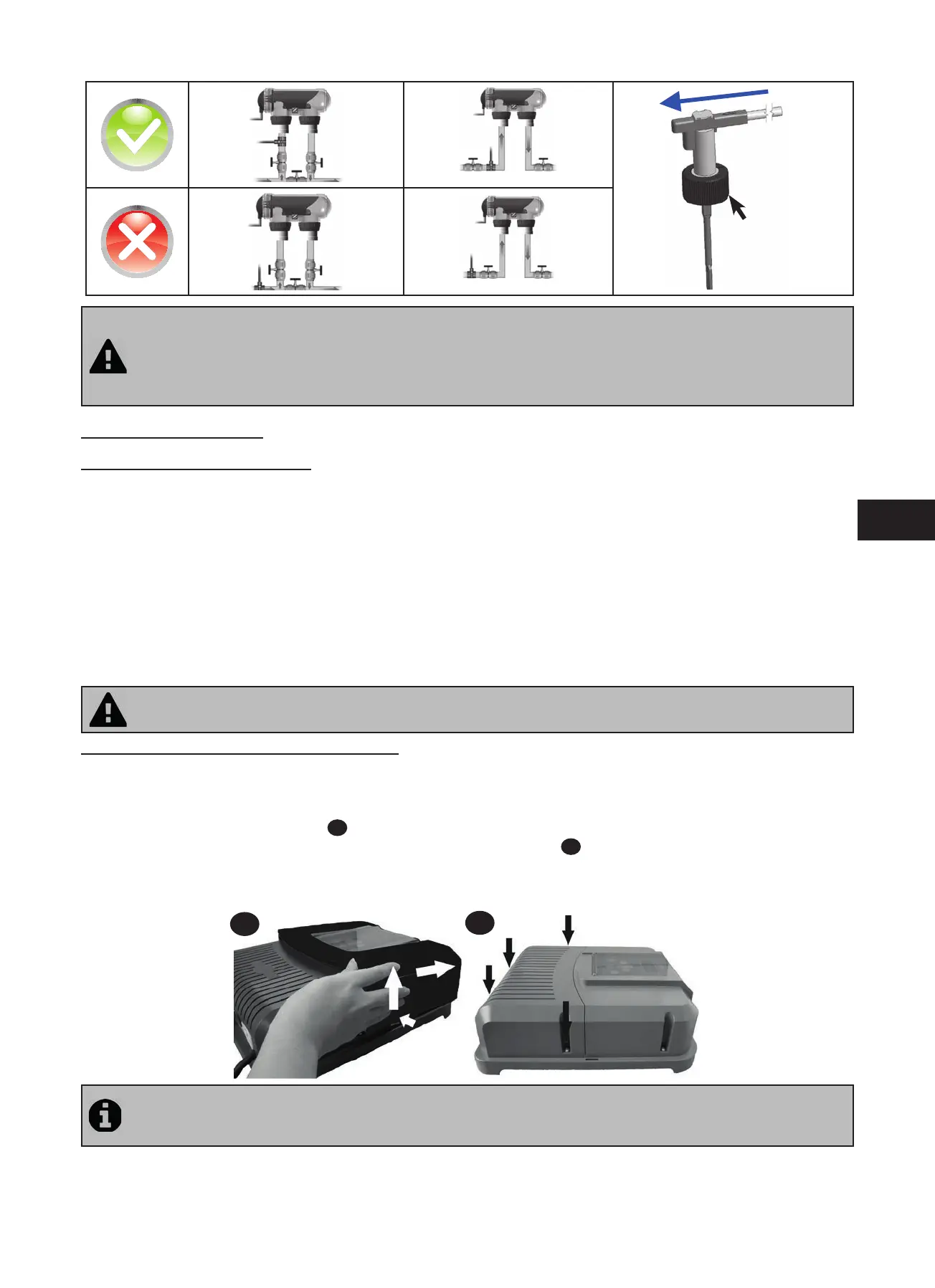
• Make sure the appliance is powered off .
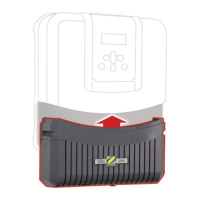
• Remove the silver protec ve cover (
1
).
• Remove the 4 lower module fi xture screws and remove the module (
2
). The bo om of the electric board is now
visible (called “PCB” on the diagrams below).
• If you have a pH or chlorine regula on module, follow the installa on steps to reassemble the module (see the module’s
installa on and user manual).
1
2
The electrolyser is compa ble with several diff erent types of electric shu er. However, certain systems may not be
compa ble. In those cases ac vate the “Low” mode manually using its specifi c bu on on the electrolyser control
panel (see “3.1.2 “Low” mode”).