3
© Copyright 2008 Zoeller Co. All rights reserved.
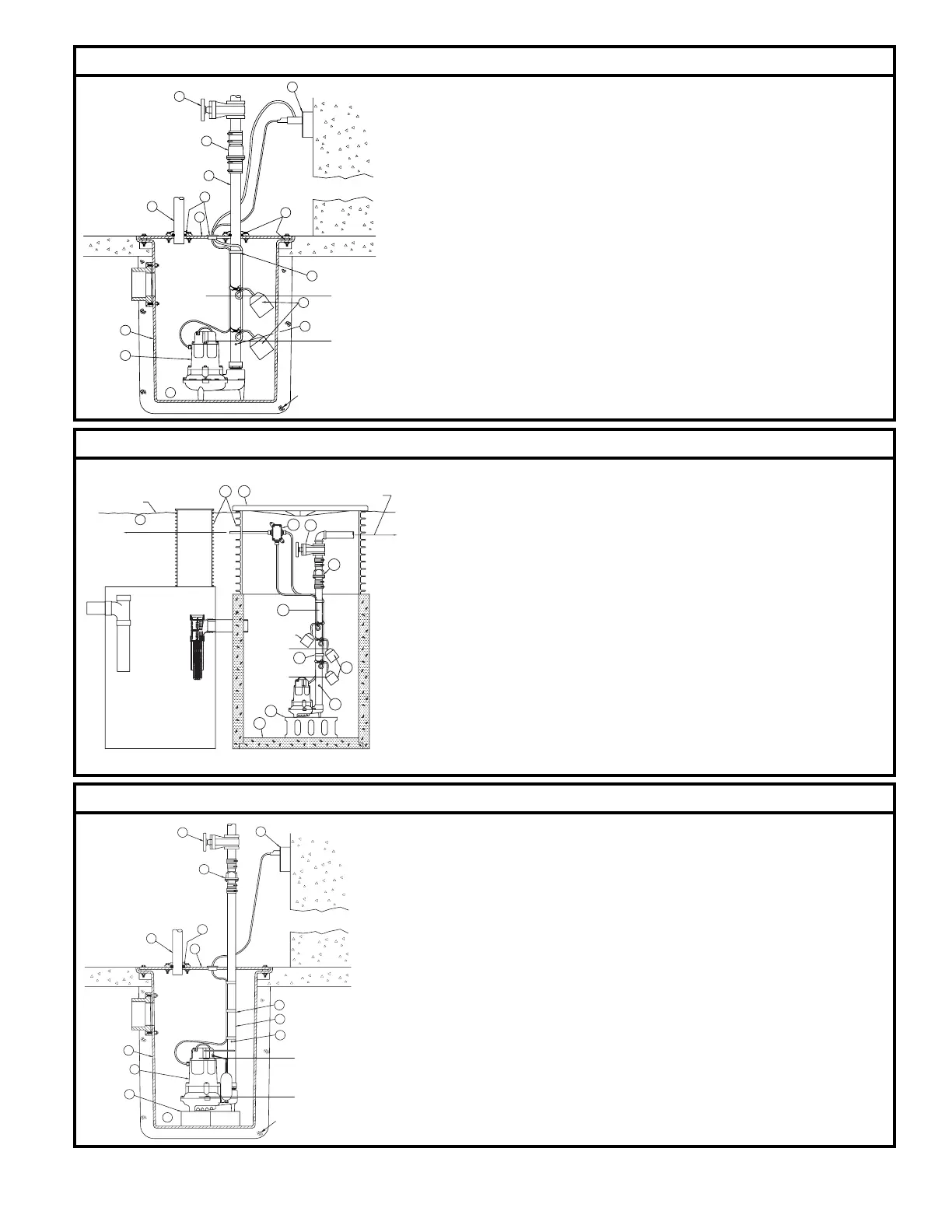
TYPICAL SEWAGE INSTALLATION-RECOMMENDED INSTALLATION
TYPICAL EFFLUENT INSTALLATION-RECOMMENDED INSTALLATION
TYPICAL DEWATERING IN STAL LA TION-RECOMMENDED INSTALLATION
All installations must comply with all applicable electrical and plumbing codes, including, but not limited to, National Electrical Code, local, regional, and/or state plumbing
codes, etc. Not intended for use in hazardous locations.
TURN
OFF
TURN
ON
1
2
3
5
11
10
8
7
6
4
4
12
13
9
4" OF GRAVEL
7
SEPTIC TANK
WW FILTER
DOSING CHAMBER
9
10
OFF
TURN
6
8
U.F. TYPE WIRE
GROUND LINE
SOURCE
TO AC
1
ON SITE DISPOSAL SYSTEM.
LEACHING FIELD, OR OTHER
MOUND SYSTEM, SAND FILTER,
TO LOW PRESSURE SYSTEM,
ALARM FLOAT
TURN
4
ON
5
3
11
212
TURN
ON
TURN
OFF
1
2
3
5
10
9
8
7
6
4
11
12
13
4" OF GRAVEL
SK290
SK291
SK292
(1) Electrical wiring and pro tec tion must be in accordance with National Electrical Code and any other
applicable state and local electrical requirements.
(2) Install proper Zoeller unicheck (combination union and check valve), preferably just above the basin
to allow easy removal of the pump for cleaning or repair. On sewage, effl uent or de w a ter ing, if high
head or below cover installation is required use 30-0152 on 1½" and 2" pipe and 30-0160 on 3" pipe.
See (6) below.
(3) All installations require a basin cover to prevent debris from falling into the basin and to prevent
accidental injury.
(4) Gas tight seals are re quired in all sewage installations to contain gases and odors.
(5) Vent gases and odors to the atmosphere through vent pipe.
(6) When a Unicheck is in stalled, drill a 3/16" dia. hole in the discharge pipe even with the top of the pump.
NOTE: THE HOLE MUST ALSO BE BELOW THE BASIN COVER AND CLEANED PE RI OD I CAL LY
(High Head unit see #3 under “Caution” on front page). Water stream will be visible from this hole
during pump run periods.
(7) Securely tape or clamp pow er cord to discharge pipe.
(8) Locate fl oat switches as shown in sketch to left. The best place for the “off” point is above the motor
housing and po si tioned 180° from the inlet. Never put “off” point below discharge on pump.
NOTE: FOR AUTOMATIC PUMPS, USE DEWATERING INSTALLATION SKETCH BELOW.
(9) Use full-size discharge pipe.
(10) Basin must be in accordance with applicable codes and specifi cations.
(11) Pump must be level and fl oat mechanism clear of sides of basin before starting pump.
(12) Basin must be clean and free of debris after installation.
(13) Gate Valve or Ball Valve to be supplied by installer and installed according to any and all codes.
NOTE: Always refer to Zoeller FM0551 and/or SSPMA Recommended Sewage Pump Installation and Maintenance.
(1) Electrical wiring and protection must be in accordance with National Electrical Code and any other
applicable state and local electrical requirements.
(2) All installations require a basin cover to prevent debris from falling into the basin, and to minimize
accidental injury.
(3) Wire pump to power through a Zoeller watertight junction box or wa ter tight splice.
NOTE: Watertight enclosure is a must in damp areas. See FM0732. See No. 8 on front page.
(4) Use full-sized discharge pipe.
(5) Install proper Zoeller unicheck (combination union and check valve), preferably just above the basin
to allow easy removal of the pump for cleaning or repair. On sewage, effl uent or de w a ter ing, if high
head or below cover installation is required use 30-0152 on 1-1/2" and 2" pipe and 30-0160 on 3"
pipe. See (6) below.
(6) When a Unicheck is in stalled, drill a 3/16" dia. hole in the discharge pipe even with the top of the pump.
The 50 and 90 Series pumps have a built in vent hole. NOTE: THE HOLE MUST ALSO BE BELOW
THE BASIN COVER AND CLEANED PERIODICALLY (High Head unit see #3 under “Caution” on
front page). Water stream will be visible from this hole during pump run periods.
(7) Securely tape or clamp pow er cord to discharge pipe.
(8) Refer to SSPMA Effl uent Sizing Manual for determining “on” - “off” switches.
(9) Install blocks or bricks under pump to provide a settling basin.
(10) Basin must be clean and free of debris after installation.
(11) Gate Valve or Ball Valve to be supplied by installer and installed according to any and all codes.
(12) Septic tank risers must be used for easy pump and fi lter access.
NOTE: See FM0531, FM0732 & FM1420 for Alarms, Controls & Junction Boxes.
(1) Electrical wiring and pro tec tion must be in accordance with National Electrical Code and any other
applicable state and local electrical requirements.
(2) Install proper Zoeller unicheck (combination union and check valve), preferably just above the basin
to allow easy removal of the pump for cleaning or re pair. On sewage, effl uent or de w a ter ing, if high
head or below cover installation is required use 30-0152 on 1-1/2" and 2" pipe and 30-0160 on 3"
pipe. See (6) below.
(3) All installations require a basin cover to prevent debris from falling into the basin, and to prevent
accidental injury.
(4) Securely tape or clamp pow er cord to discharge pipe clear of the fl oat mech a nism.
(5) Minimum 18" dia. x 24" deep basin. Larger depths may be required.
(6) When a Unicheck is in stalled, drill a 3/16" dia. hole in the discharge pipe even with the top of the pump.
The 50 and 90 series pumps have a built in vent hole. NOTE: THE HOLE MUST ALSO BE BELOW
THE BASIN COVER AND CLEANED PE RI OD I CAL LY (High Head unit see #3 under “Caution” on
front page). Water stream will be visible from this hole during pump run periods.
(7) Use a full-size discharge pipe.
(8) Pump must be level and fl oat mechanism clear of sides of basin before starting pump.
(9) Install blocks or bricks under pump to provide a settling basin.
(10) Basin must be clean and free of debris after installation.
(11) Gate Valve or Ball Valve to be supplied by installer and installed according to any and all codes.
(12) Gas tight seals are re quired in all sewage installations to contain gases and odors.
(13) Vent gases and odors to the atmosphere through vent pipe.
NOTE: See FM0531, FM0732 & FM1420 for Alarms, Controls & Junction Boxes.
 Loading...